
Concept explainers
Videos
The saturated output voltages are
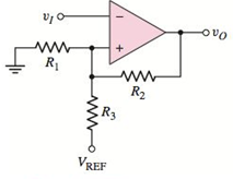
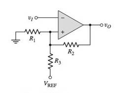
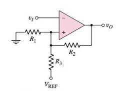
Figure P15.47
(a)
To find: The expression for given crossover voltages.
Answer to Problem 15.47P
The upper crossover voltage of Schmitt trigger is
The lower crossover voltage of Schmitt trigger is
Explanation of Solution
Given:
The given circuit is shown below.
Calculation:
From the above circuit
The inverting node is,
Applying Kirchhoff's current law at non-inverting node:
Substitute
When
The upper crossover voltage of Schmitt trigger is
When
The lower crossover voltage of Schmitt trigger is
Conclusion:
The upper crossover voltage of Schmitt trigger is
The lower crossover voltage of Schmitt trigger is
(b)
To find: The values of
Answer to Problem 15.47P
The required values are
Explanation of Solution
Given:
Saturated output voltage is,
Reference voltage is,
One resistor value is,
Switching point is,
Hysteresis width is
Calculation:
Substitute
Hence,
Substitute
Substitute
Assuming
Hence, we get
Substitute
Therefore, value of
Substitute
Therefore, the value of
Conclusion:
Therefore, the required values are
(c)
To sketch: The voltage transfer characteristics.
Answer to Problem 15.47P
The voltage transfer characteristics are shown in Figure 1.
Explanation of Solution
Given:
Calculation:
The upper crossover voltage of Schmitt trigger is
Therefore, the upper crossover voltage of Schmitt trigger is
The lower crossover voltage of Schmitt trigger is
Therefore, the lower crossover voltage of Schmitt trigger is
Figure 1
Conclusion:
Therefore, the voltage transfer characteristics are shown in Figure 1.
Want to see more full solutions like this?
Chapter 15 Solutions
Microelectronics: Circuit Analysis and Design


- 60 fi fs f2 Qs = f = 12,000 Hz the cutoff frequency f2 =.............Hz ▬▬ Q Search book.pat digital-fundamental...arrow_forwardA boost converter has an input voltage Vb-5V. The average load current is lo-0SA. The switching frequency is 25 kHz. Suppose that a regulator is added (L=0.15 mH and C-0.22 mF) and that the current is continuous. if the average output voltage is Vo =15V, then the ripple current of the inductor delta) is equal to: Select one: O a. None of these O b.0.89A O C. 1.41A O d. 0.56Aarrow_forwardWhat percent reduction in output/input signal magnitude would you expect at the 1800 cycle/min frequency from a thermocouple with a 1/9 of a second time constant? Assume T= 3 and static sensitivity, K 1. 30% 5% 70% 95%arrow_forward
- a) Design a Butterworth band-pass filter using the TL084 amplifier and draw it with the following specifications:Lower frequency= 60 HzUpper Frequency = 5K HzQ=?Resonant frequency =?arrow_forwardHome Work 1/ what js meant by Nyquí st rate ? Q2/ what s meant by Pulse Moduletim ? why we need PM?arrow_forwardExplain how the Active Low Pass Filter works in detail, as shown in a drawingarrow_forward
- R₁ 22 ΚΩ VIN- R₂ www 220 ΚΩ -VOUT Figure 15.4: A non-inverting amplifier circuit. Consider the op amp circuit in figure 15.4 for the following: 1. If the op amp has a gain bandwidth of 220 kHz, what will the bandwidth of the whole amplifier circuit be?arrow_forward6. Refer to the RC Phase-shift Oscillator below. A Vin R₁ + Rf 6.a. Derive the feedback factor formula for this circuit. 6.b. Draw the output waveform. C C mm C Vout wwwwwarrow_forwardDraw The modulation and demodulation block diagrams of Amplit de Modulation -Vestigial side band (AM-VSB)arrow_forward
- The clamping circuit clamps or shift the input sinusoidal signal up or down. Farrow_forwardDraw a diagram for astable multivibrator using 555 timer. Find the oscillation frequency of the output signal and its duty cycle when the external capacitor is 0.01 uF, the R1 and R2 are 10 kn and 50 kn respectively. While the decoupling capacitor equal 0.1 µF. What happened to the duty cycle when R2 become 1M02?arrow_forwardWhat is the output impedance seen by RL?arrow_forward
 Introductory Circuit Analysis (13th Edition)Electrical EngineeringISBN:9780133923605Author:Robert L. BoylestadPublisher:PEARSON
 Delmar's Standard Textbook Of ElectricityElectrical EngineeringISBN:9781337900348Author:Stephen L. HermanPublisher:Cengage Learning
 Programmable Logic ControllersElectrical EngineeringISBN:9780073373843Author:Frank D. PetruzellaPublisher:McGraw-Hill Education
 Fundamentals of Electric CircuitsElectrical EngineeringISBN:9780078028229Author:Charles K Alexander, Matthew SadikuPublisher:McGraw-Hill Education
 Electric Circuits. (11th Edition)Electrical EngineeringISBN:9780134746968Author:James W. Nilsson, Susan RiedelPublisher:PEARSON
 Engineering ElectromagneticsElectrical EngineeringISBN:9780078028151Author:Hayt, William H. (william Hart), Jr, BUCK, John A.Publisher:Mcgraw-hill Education,