
Concept explainers
Videos
(a)
The maximum allowed tolerance in the
(a)
Answer to Problem 16.99P
The maximum allowed value of the tolerance is
Explanation of Solution
Calculation:
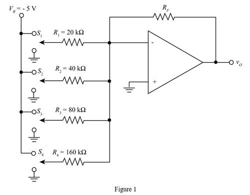
The given diagram is shown in Figure 1
The expression to determine the analog output voltage
Substitute
The expression to determine the value of the least significant digit is given by,
Substitute
The expression to determine the value of the output analog voltage with maximum error is given by,
Substitute
The expression to determine the value of the output analog voltage with maximum error
Substitute
Substitute
The expression to determine the percentage allowed tolerance in the value of resistance
Substitute
Substitute
Substitute
Conclusion:
Therefore, the maximum allowed value of the tolerance is
(b)
The maximum allowed tolerance in the value of
(b)
Answer to Problem 16.99P
The maximum allowed value of the tolerance is
Explanation of Solution
Calculation:
The expression to determine the analog output voltage
Substitute
The expression to determine the value of the output analog voltage with maximum error is given by,
Substitute
The expression to determine the value of the output analog voltage with maximum error
Substitute
Substitute
The expression to determine the percentage allowed tolerance in the value of resistance
Substitute
Substitute
Substitute
Conclusion:
Therefore, the maximum allowed value of the tolerance is
Want to see more full solutions like this?
Chapter 16 Solutions
Microelectronics: Circuit Analysis and Design


- For 4-bit DAC Binary Weighted Resistor Method, if the Vref = 20V, and R = 5 Kohm, what is the output current for the following sequence: 1001 0.0105 A 0.0045 A 0.00205 A 0.004 Aarrow_forwardAccording to what is given, RI Rc Vcc g1601 C2 R2. RE Ry 0100555-9870479447 CE g1601 g160100555 - 987047944 160. Rg = 1k R1 = 100k RC = 9k RE = 1k Ry = 10k VCC = 20V g160100555 - 9870479447 287047 For the transistor used in the circuit, hfe = hFE = s160100555-9870479447 g1601005 08704 a. g160100555- 9870479447 | Find IC current • b. Find the value of the resistance = hoe = 0, VBE 10055 D. Find the input resistance (ri). Find the voltage gain (Kv). = 10V and R2. 100555-987047944/ 0100555-987047944 20100555-987047944 916055 916055 916055arrow_forwardIn a self-bias n-channel JFET, the operating point is to be set at ID = 1.5 mA and VDS =10 V. The JFET parameters are IDSS =5mA and VGS(off) =−2V. Find the values of RD. Given that VDD = 20 V.arrow_forward
- 10 k2, RE = R, = 150 2, r'e = 50 2, and Bac = 50. The For a common-emitter anmplifier, R value of the voltage gain is +Vcc Rc C3 R oVout REI R2 RE2 Select one: a. 67 b. 100 C. 50 d. 28.5arrow_forwardA JFET has a 5 V. when Vas =0, what is Vos at th Point where the drain current brcome Constant? specified Pinch - off Voltage ofarrow_forwardStringing of cells in a PV panel Draw the tabbing and bus-bar wires for a 72 cell module using three substrings and a junction box mounted in the typical central location. Each substring is protected by a bypass diode. No precision drawing is needed (i.e. you don't need to draw every single cell, the main arrangement of substring and how you connect to the jnction-box is relevant.arrow_forward
- VI Ru Ri Vz I, Io R2 = 3837.79 O. R3 = 3989.3 Q. %3D R4 = 2898.06 Q. V1 = 4.8 V. V2 = 8.1 V. 11 = 0.0099 A Determine the following: a.) The output current lo %3Darrow_forwardA JFET has VGS(off) = -5 v and IDSS = 20mA. What are gate voltage and draincurrent at the half cutoff point?arrow_forwardSuggest circuits that protect SCR against dv/dtarrow_forward
 Introductory Circuit Analysis (13th Edition)Electrical EngineeringISBN:9780133923605Author:Robert L. BoylestadPublisher:PEARSON
 Delmar's Standard Textbook Of ElectricityElectrical EngineeringISBN:9781337900348Author:Stephen L. HermanPublisher:Cengage Learning
 Programmable Logic ControllersElectrical EngineeringISBN:9780073373843Author:Frank D. PetruzellaPublisher:McGraw-Hill Education
 Fundamentals of Electric CircuitsElectrical EngineeringISBN:9780078028229Author:Charles K Alexander, Matthew SadikuPublisher:McGraw-Hill Education
 Electric Circuits. (11th Edition)Electrical EngineeringISBN:9780134746968Author:James W. Nilsson, Susan RiedelPublisher:PEARSON
 Engineering ElectromagneticsElectrical EngineeringISBN:9780078028151Author:Hayt, William H. (william Hart), Jr, BUCK, John A.Publisher:Mcgraw-hill Education,