
Mechanics of Materials (10th Edition)
10th Edition
ISBN: 9780134319650
Author: Russell C. Hibbeler
Publisher: PEARSON
expand_more
expand_more
format_list_bulleted
Videos
Textbook Question
Chapter 3, Problem 3.2RP
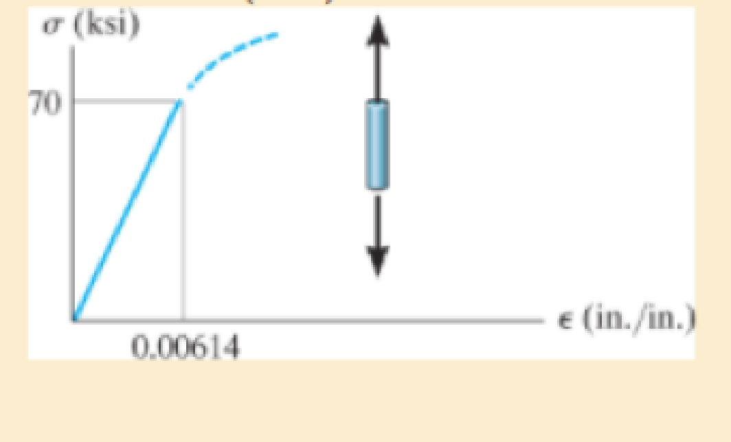
The elastic portion of the tension stress-strain diagram for an aluminum alloy is shown in the figure. The specimen used for the test has a gage length of 2 in. and a diameter of 0.5 in. If the applied load is 10 kip, determine the new diameter of the specimen. The shear modulus is Gal = 3.8 (103) ksi
Expert Solution & Answer
Want to see the full answer?
Check out a sample textbook solution
Students have asked these similar questions
The elastic portion of the stress-strain diagram for an aluminum alloy is shown
in the figure. The specimen from which it was obtained has an original diameter of 12.7
mm and a gage length of 50.8 mm. If a load of P=60 kN is applied to the specimen,
determine its new diameter and length. Take v = 0.35.
o (MPa)
490
e (mm/mm)
0.007
The elastic portion of the stress–strain diagram for an aluminum alloy is shown in the figure. The specimen from which it was obtained has an original diameter of 12.7 mm and a gage length of 50.8 mm. If a load of P = 60 kN is applied to the specimen, determine its new diameter and length. Taken = 0.35.
R8-1. The elastic portion of the tension stress-strain
diagram for an aluminum alloy is shown in the figure. The
specimen used for the test has a gauge length of 50 mm and
a diameter of 12.5 mm. When the applied load is 40 kN, the
new diameter of the specimen is 12.4800 mm. Compute the
shear modulus G, for the aluminum.
a (MPa)
350
(mm/mm)
0.00480
Chapter 3 Solutions
Mechanics of Materials (10th Edition)
Ch. 3.4 - Define a homogeneous material.Ch. 3.4 - Indicate the points on the stress-strain diagram...Ch. 3.4 - Define the modulus of elasticity E.Ch. 3.4 - At room temperature, mild steel is a ductile...Ch. 3.4 - Engineering stress and strain are calculated using...Ch. 3.4 - As the temperature increases the modulus of...Ch. 3.4 - A 100-mm-long rod has a diameter of 15 mm. If an...Ch. 3.4 - A bar has a length of 8 in. and cross-sectional...Ch. 3.4 - A 10-mm-diameter rod has a modulus of elasticity...Ch. 3.4 - The material for the 50-mm-long specimen has the...
Ch. 3.4 - The material for the 50-mm-long specimen has the...Ch. 3.4 - If the elongation of wire BC is 0.2 mm after the...Ch. 3.4 - A tension test was performed on a steel specimen...Ch. 3.4 - Data taken from a stress-strain test for a ceramic...Ch. 3.4 - Data taken from a stress-strain test for a ceramic...Ch. 3.4 - The stress-strain diagram for a steel alloy having...Ch. 3.4 - The stress-strain diagram for a steel alloy having...Ch. 3.4 - The stress-strain diagram for a steel alloy having...Ch. 3.4 - The rigid beam is supported by a pin at C and an...Ch. 3.4 - The rigid beam is supported by a pin at C and an...Ch. 3.4 - Acetal plastic has a stress-strain diagram as...Ch. 3.4 - The stress-strain diagram for an aluminum alloy...Ch. 3.4 - The stress-strain diagram for an aluminum alloy...Ch. 3.4 - The stress-strain diagram for an aluminum alloy...Ch. 3.4 - A bar having a length of 5 in. and cross-sectional...Ch. 3.4 - The rigid pipe is supported by a pin at A and an...Ch. 3.4 - The rigid pipe is supported by a pin at A and an...Ch. 3.4 - Direct tension indicators are sometimes used...Ch. 3.4 - The rigid beam is supported by a pin at C and an...Ch. 3.4 - The rigid beam is supported by a pin at C and an...Ch. 3.4 - The stress-strain diagram for a bone is shown, and...Ch. 3.4 - The stress-strain diagram for a bone is shown and...Ch. 3.4 - The two bars are made of a material that has the...Ch. 3.4 - The two bars are made of a material that has the...Ch. 3.4 - The pole is supported by a pin at C and an A-36...Ch. 3.4 - The bar DA is rigid and is originally held in the...Ch. 3.7 - A 100-mm-long rod has a diameter of 15 mm. If an...Ch. 3.7 - A solid circular rod that is 600 mm long and 20 mm...Ch. 3.7 - A 20-mm-wide block is firmly bonded to rigid...Ch. 3.7 - A 20-mm-wide block is bonded to rigid plates at...Ch. 3.7 - The acrylic plastic rod is 200 mm long and 15 mm...Ch. 3.7 - The plug has a diameter of 30 mm and fits within a...Ch. 3.7 - The elastic portion of the stress-strain diagram...Ch. 3.7 - The elastic portion of the stress-strain diagram...Ch. 3.7 - The brake pads for a bicycle tire are made of...Ch. 3.7 - The lap joint is connected together using a 1.25...Ch. 3.7 - The lap joint is connected together using a 1.25...Ch. 3.7 - The rubber block is subjected to an elongation of...Ch. 3.7 - The shear stress-strain diagram for an alloy is...Ch. 3.7 - A shear spring is made from two blocks of rubber,...Ch. 3 - The elastic portion of the tension stress-strain...Ch. 3 - The elastic portion of the tension stress-strain...Ch. 3 - The rigid beam rests in the horizontal position on...Ch. 3 - The wires each have a diameter of 12 in., length...Ch. 3 - The wires each have a diameter of 12 in., length...Ch. 3 - diameter steel bolts. If the clamping force in...Ch. 3 - The stress-strain diagram for polyethylene, which...Ch. 3 - The pipe with two rigid caps attached to its ends...Ch. 3 - The 8-mm-diameter bolt is made of an aluminum...Ch. 3 - An acetal polymer block is fixed to the rigid...
Knowledge Booster


Learn more about
Need a deep-dive on the concept behind this application? Look no further. Learn more about this topic, mechanical-engineering and related others by exploring similar questions and additional content below.Similar questions
- The stress-strain diagram for an aluminum alloy specimen having an original diameter of 0.5 in. and a gauge length of 2 in. is given in the figure. If the specimen is loaded until it is stressed to 60 ksi, determine the approximate amount of elastic recovery and the increase in the gage length after it is unloaded.arrow_forwardThe elastic portion of the tension stress–strain diagram for an aluminum alloy is shown in the figure. The specimen used for the test has a gage length of 2 in. and a diameter of 0.5 in. When the applied load is 9 kip, the new diameter of the specimen is 0.49935 in. Calculate the shear modulus Gal for the aluminum.arrow_forward= 2-Consider a 45° off-axis tensile test coupon. Three strain gages attached as shown below are reading el 0.00647, 2= -0.00324, and 3 = 0.008095 at stress level of ox=100 MPa. Determine the off-axis modulus of elasticity Ex the off-axis major Poisson's ratio vxy and coefficient of mutual influence of the second kind nxy,x 2 √²-01-² y 45° €2 0₂arrow_forward
- The stress-strain diagram for a steel alloy having an original diameter of 0.5 in. and a gage length of 2 in. is given in the figure. Determine approximately the modulus of elasticity for the material, the load on the specimen that causes yielding, and the ultimate load the specimen will support. o (ksi) 80 70 60 50 40 30 20 10 e (in./in.) 0 0.04 0.08 0.12 0.16 0.20 0.24 0.28 0 .0.0005 0.0010.0015 0.002 0.0025 0.0030.0035arrow_forwardThe stress–strain diagram for a steel alloy having an original diameter of 0.5 in. and a gage length of 2 in. is given in the figure. If the specimen is loaded until it is stressed to 70 ksi, determine the approximate amount of elasticrecovery and the increase in the gage length after it is unloaded.arrow_forwardNylon strips are fused to glass plates. When moderately heated the nylon will become soft while the glass stays approximately rigid. Determine the average shear strain in the nylon due to the load P when the assembly deforms as indicated. 2 mm P. 3 mm 5 mm 3 mm 5 mm 3 mmarrow_forward
- A uniform edge load of 400 lb/in. and 300 lb/in. is applied to the thin plane specimen shown below. If the specimen is originally square and has dimensions of a = 2 in., b = 2 in., and a thickness of t = 0.25 in., determine its new dimensions a', b', and t' after the load is applied. Elastic modulus E = 600 x 103 psi and Poisson's ratio v = 0.3. 300 lb/in. a = 2 in. 400 lb/in. 300 lb/in. b = 2 in. 400 lb/in.arrow_forwardThe strain gauge is placed on the surface of a thin-walled steel boiler as shown The gauge is 0.5 in long and it elongates 0.17(103) in when a pressure is applied. The boiler has a thickness of 0.5 in and inner diameter of 60 in Est = 29(10³) ksi, st = 0.3 (Figure 1) Figure 0.5 in. X 1 of 1 60 in. Determine the pressure in the boiler. Express your answer using three significant figures and include the appropriate units. P = Submit ▾ Part B 0 Value HA Submit Request Answer Ymax in plane Determine the maximum x y in plane shear strain in the material. Express your answer using three significant figures. Units ΑΣΦ | 4 Request Answer ? vec WYCZA ?arrow_forward3. The elastic portion of the stress-strain diagram for a steel alloy is shown in the figure below. The specimen from which it was obtained had an original diameter of 13 mm and a gauge length of 50 mm. If a load of P = 20 kN is applied to the specimen, determine its diameter and gauge length. Take v = 0.4 σ (MPa) 400 0.002 e(mm/mm)arrow_forward
- The elastic portion of the stress–strain diagram for an aluminum alloy is shown in the figure. The specimen from which it was obtained has an original diameter of 12.7 mm andagagelengthof50.8mm.IfaloadofP=60kNisapplied to the specimen, determine its new diameter and length. Take n = 0.35.arrow_forwardThe stress–strain diagram for an aluminum alloy specimen having an original diameter of 0.5 in. and a gauge length of 2 in. is given in the figure. Determine approximately the modulus of resilience and the modulus of toughness for the material.arrow_forwardThe elastic region of the tension stress-strain diagram for an aluminum alloy is shown in (Figure 1). The specimen used for the test has a gage length of 2 in. and a diameter of 0.5 in. The shear modulus is Gal = 3.8 (10³) ksi. Figure σ (ksi) 70 VI 0.00614 1 of 1 € (in./in.) Part A If the applied load is 15 kip, determine the new diameter of the specimen. Express your answer in inches to four significant figures. IVE ΑΣΦ ↓↑ vec d' = Submit Provide Feedback Request Answer ? in.arrow_forward
arrow_back_ios
SEE MORE QUESTIONS
arrow_forward_ios
Recommended textbooks for you
 Elements Of ElectromagneticsMechanical EngineeringISBN:9780190698614Author:Sadiku, Matthew N. O.Publisher:Oxford University Press
 Mechanics of Materials (10th Edition)Mechanical EngineeringISBN:9780134319650Author:Russell C. HibbelerPublisher:PEARSON
 Thermodynamics: An Engineering ApproachMechanical EngineeringISBN:9781259822674Author:Yunus A. Cengel Dr., Michael A. BolesPublisher:McGraw-Hill Education
 Control Systems EngineeringMechanical EngineeringISBN:9781118170519Author:Norman S. NisePublisher:WILEY
 Mechanics of Materials (MindTap Course List)Mechanical EngineeringISBN:9781337093347Author:Barry J. Goodno, James M. GerePublisher:Cengage Learning
 Engineering Mechanics: StaticsMechanical EngineeringISBN:9781118807330Author:James L. Meriam, L. G. Kraige, J. N. BoltonPublisher:WILEY
Elements Of Electromagnetics
Mechanical Engineering
ISBN:9780190698614
Author:Sadiku, Matthew N. O.
Publisher:Oxford University Press
Mechanics of Materials (10th Edition)
Mechanical Engineering
ISBN:9780134319650
Author:Russell C. Hibbeler
Publisher:PEARSON
Thermodynamics: An Engineering Approach
Mechanical Engineering
ISBN:9781259822674
Author:Yunus A. Cengel Dr., Michael A. Boles
Publisher:McGraw-Hill Education
Control Systems Engineering
Mechanical Engineering
ISBN:9781118170519
Author:Norman S. Nise
Publisher:WILEY
Mechanics of Materials (MindTap Course List)
Mechanical Engineering
ISBN:9781337093347
Author:Barry J. Goodno, James M. Gere
Publisher:Cengage Learning
Engineering Mechanics: Statics
Mechanical Engineering
ISBN:9781118807330
Author:James L. Meriam, L. G. Kraige, J. N. Bolton
Publisher:WILEY
An Introduction to Stress and Strain; Author: The Efficient Engineer;https://www.youtube.com/watch?v=aQf6Q8t1FQE;License: Standard YouTube License, CC-BY