
Mechanics of Materials (10th Edition)
10th Edition
ISBN: 9780134319650
Author: Russell C. Hibbeler
Publisher: PEARSON
expand_more
expand_more
format_list_bulleted
Concept explainers
Videos
Textbook Question
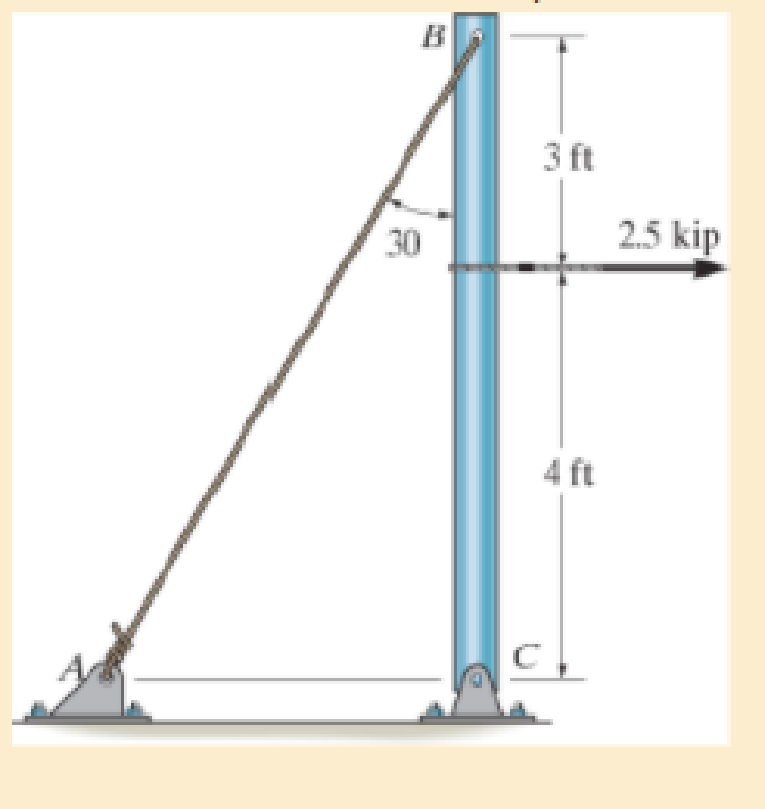
Chapter 3.4, Problem 3.23P
The pole is supported by a pin at C and an A-36 steel guy wire AB. If the wire has a diameter of 0.2 in., determine how much it stretches when a horizontal force of 2.5 kip acts on the pole
Expert Solution & Answer
Want to see the full answer?
Check out a sample textbook solution
Students have asked these similar questions
The strut is supported by a pin at C and an A-36 steel guy wire AB. If the wire has a diameter of 1,2 m , determine how much it stretches when the distributed load acts on the strut.
3. At temperature T₁, the two rigidly connected rods just fit the
rigid supports. If both sections are identical except for the
diameter, prove that the following equations are true when
temperature rises to T₂.
a.
F=
b. OAB
C. OBC
A
x(T₂-T₁)лd²E
20
x(T₂-T₁)E
5
9x(T₂-T₁)E
5
-1/2-
d
B
1/12-
d
C
If P is equivalent to 94 kN, the diameter at pin B is Blank 1 mm.
Chapter 3 Solutions
Mechanics of Materials (10th Edition)
Ch. 3.4 - Define a homogeneous material.Ch. 3.4 - Indicate the points on the stress-strain diagram...Ch. 3.4 - Define the modulus of elasticity E.Ch. 3.4 - At room temperature, mild steel is a ductile...Ch. 3.4 - Engineering stress and strain are calculated using...Ch. 3.4 - As the temperature increases the modulus of...Ch. 3.4 - A 100-mm-long rod has a diameter of 15 mm. If an...Ch. 3.4 - A bar has a length of 8 in. and cross-sectional...Ch. 3.4 - A 10-mm-diameter rod has a modulus of elasticity...Ch. 3.4 - The material for the 50-mm-long specimen has the...
Ch. 3.4 - The material for the 50-mm-long specimen has the...Ch. 3.4 - If the elongation of wire BC is 0.2 mm after the...Ch. 3.4 - A tension test was performed on a steel specimen...Ch. 3.4 - Data taken from a stress-strain test for a ceramic...Ch. 3.4 - Data taken from a stress-strain test for a ceramic...Ch. 3.4 - The stress-strain diagram for a steel alloy having...Ch. 3.4 - The stress-strain diagram for a steel alloy having...Ch. 3.4 - The stress-strain diagram for a steel alloy having...Ch. 3.4 - The rigid beam is supported by a pin at C and an...Ch. 3.4 - The rigid beam is supported by a pin at C and an...Ch. 3.4 - Acetal plastic has a stress-strain diagram as...Ch. 3.4 - The stress-strain diagram for an aluminum alloy...Ch. 3.4 - The stress-strain diagram for an aluminum alloy...Ch. 3.4 - The stress-strain diagram for an aluminum alloy...Ch. 3.4 - A bar having a length of 5 in. and cross-sectional...Ch. 3.4 - The rigid pipe is supported by a pin at A and an...Ch. 3.4 - The rigid pipe is supported by a pin at A and an...Ch. 3.4 - Direct tension indicators are sometimes used...Ch. 3.4 - The rigid beam is supported by a pin at C and an...Ch. 3.4 - The rigid beam is supported by a pin at C and an...Ch. 3.4 - The stress-strain diagram for a bone is shown, and...Ch. 3.4 - The stress-strain diagram for a bone is shown and...Ch. 3.4 - The two bars are made of a material that has the...Ch. 3.4 - The two bars are made of a material that has the...Ch. 3.4 - The pole is supported by a pin at C and an A-36...Ch. 3.4 - The bar DA is rigid and is originally held in the...Ch. 3.7 - A 100-mm-long rod has a diameter of 15 mm. If an...Ch. 3.7 - A solid circular rod that is 600 mm long and 20 mm...Ch. 3.7 - A 20-mm-wide block is firmly bonded to rigid...Ch. 3.7 - A 20-mm-wide block is bonded to rigid plates at...Ch. 3.7 - The acrylic plastic rod is 200 mm long and 15 mm...Ch. 3.7 - The plug has a diameter of 30 mm and fits within a...Ch. 3.7 - The elastic portion of the stress-strain diagram...Ch. 3.7 - The elastic portion of the stress-strain diagram...Ch. 3.7 - The brake pads for a bicycle tire are made of...Ch. 3.7 - The lap joint is connected together using a 1.25...Ch. 3.7 - The lap joint is connected together using a 1.25...Ch. 3.7 - The rubber block is subjected to an elongation of...Ch. 3.7 - The shear stress-strain diagram for an alloy is...Ch. 3.7 - A shear spring is made from two blocks of rubber,...Ch. 3 - The elastic portion of the tension stress-strain...Ch. 3 - The elastic portion of the tension stress-strain...Ch. 3 - The rigid beam rests in the horizontal position on...Ch. 3 - The wires each have a diameter of 12 in., length...Ch. 3 - The wires each have a diameter of 12 in., length...Ch. 3 - diameter steel bolts. If the clamping force in...Ch. 3 - The stress-strain diagram for polyethylene, which...Ch. 3 - The pipe with two rigid caps attached to its ends...Ch. 3 - The 8-mm-diameter bolt is made of an aluminum...Ch. 3 - An acetal polymer block is fixed to the rigid...
Knowledge Booster


Learn more about
Need a deep-dive on the concept behind this application? Look no further. Learn more about this topic, mechanical-engineering and related others by exploring similar questions and additional content below.Similar questions
- The pole is supported by a pin at C and an A-36 steel guy wire AB. B. 3 ft 30 2.5 kip 4 ft Part A If the wire has a diameter of 0.3 in., determine how much it stretches when a horizontal force of 2.5 kip acts on the pole. Express your answer to three significant figures and include appropriate units.arrow_forwardQ2/ The 10-mm-diameter bolt is made of an aluminum alloy. It fits through a magnesium sleeve that has an inner diameter of 15 mm and an outer diameter of 25 mm. The original lengths of the bolt and sleeve are 80 mm and 50 mm, respectively. If after the nut on the bolt is tightened the tension in the bolt is 10 kN, determine the change in dimension of the cross-section of the bolt and the sleeve. Assume the material at A is rigid. Ea = 70 GPa, Emg = 45 GPa, Ga = 26 GPa, Gmg = 17 GPa. 50 mm 30 mmarrow_forwardQ2/ The 10-mm-diameter bolt is made of an aluminum alloy. It fits through a magnesium sleeve that has an inner diameter of 15 mm and an outer diameter of 25 mm. The original lengths of the bolt and sleeve are 80 mm and 50 mm, respectively. If after the nut on the bolt is tightened the tension in the bolt is 10 kN, determine the change in dimension of the cross-section of the bolt and the sleeve. Assume the material at A is rigid. E = 70 GPa, Emg = 45 GPa, Ga 26 GPa, Gmg= 17 GPa. 50 mm 30 mmarrow_forward
- Determine the magnitude of the pin force at B. 0.43 m 0.61 m 125 N-In B 0.43 m 0.43 marrow_forwardThe linkage is made of two pin-connected A-36 steel members, each having a cross-sectional area of 1000 mm^2. Determine the magnitude of the force P needed to displace point A 0.425 mm downward.arrow_forwardA small stepladder has vertical rails and horizontal steps formed from a C-section aluminum channel. Two rivets, one in front and one in back, secure the ends of each step. The rivets attach the steps to the left and right hand rails. A 225 lb person stands in the center of a step. If rivets are formed of 6061-T6 aluminum, what should be the diameter d of the rivets? Use a factor of safety of 8 and round your answer to the nearest 1/16 of an in.arrow_forward
- If the elongation of wire BC is 0.2 mm after the force P is applied, determine the magnitude of P. The wire is A-36 steel and has a diameter of 3 mm.arrow_forwardNeglect the thickness of the bar. Take ua=ub=u suppose that b= 1 ftarrow_forwardThe two steel shafts (1) and (2) each Ø10 should be connected to each other with the help of the sleeve (3) (Øinner = 10, Øoutside = 15) also made of steel and two rivets at the points shown. The shaft (1) is firmly clamped on the left- hand side, the force F = 100 N acts on shaft 2 in the direction of the arrow. How are the brass round rivets to be dimensioned so that a safety of the coupling against failure of S = 10 is achieved? hole for rivets 1 F 3 a) What type of connection does a riveted connection have? b) What type of load does the rivet have? c) What is the diameter of the rivets? d) Which areas of the rivet are loaded? (Draw in figure and formula) e) Dimension the rivetarrow_forward
- The de diagram for a collagen fiber bundle from which a human tendon is composed is shown. If a segment of the Achilles tendon at A has a length of 6.5 in. and an approximate cross-sectional area of 0.229 in², determine its elongation if the foot supports a load of 125 lb, which causes a tension in the tendon of 343.75 lb. (ksi) 4.50 3.75 3.00 2.25 1.50 0.75 0.05 0.10 150b (in./in.)arrow_forwardThe rigid pipe is supported by a pin at A and an A-36 steel guy wire BD. If the wire has a diameter of 0.25 in., determine how much it stretches when a load of P = 600 lb acts on the pipe.arrow_forwardThe structure is supported by a pin at C and a cable attached to A. The cable runs over the small pulley D. Find the internal force systems acting on sections 1 and 2.arrow_forward
arrow_back_ios
SEE MORE QUESTIONS
arrow_forward_ios
Recommended textbooks for you
 International Edition---engineering Mechanics: St...Mechanical EngineeringISBN:9781305501607Author:Andrew Pytel And Jaan KiusalaasPublisher:CENGAGE L
International Edition---engineering Mechanics: St...
Mechanical Engineering
ISBN:9781305501607
Author:Andrew Pytel And Jaan Kiusalaas
Publisher:CENGAGE L
EVERYTHING on Axial Loading Normal Stress in 10 MINUTES - Mechanics of Materials; Author: Less Boring Lectures;https://www.youtube.com/watch?v=jQ-fNqZWrNg;License: Standard YouTube License, CC-BY