
Concept explainers
Videos
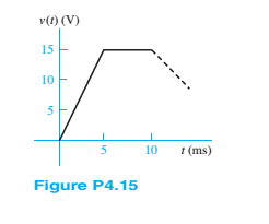
The voltage across a generic element X has the waveform shown in Figure P4.15. For
a.
b.
c. 7-mH inductor.
(a)
The current through the given element for the given voltage waveform.
To plot:
A graph of current through the element for
Answer to Problem 4.15HP
The current through the given element for the given voltage waveform is
A graph of current through the element for
Explanation of Solution
Given information:
Element is resistor and its value is
The given voltage waveform is shown below.

Calculation:
Consider the given graph for the voltage.
For
For
So, voltage can be written as
The given element is resistor. The current across it will be
Voltage
For
For
Current
A graph of current with respect to time is shown below.
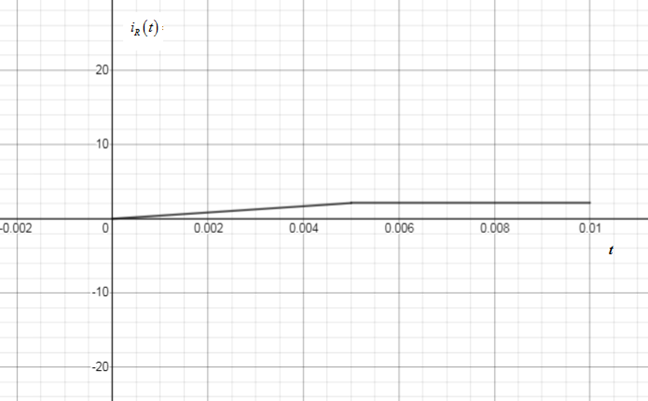
Figure 1
(b)
The current through the given element for the given voltage waveform.
To plot:
A graph of current through the element for
Answer to Problem 4.15HP
The current through the given element for the given voltage waveform is
A graph of current through the element for
Explanation of Solution
Given information:
Element is capacitor and its value is
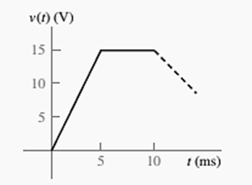
The given voltage waveform is shown below.

Calculation:
Consider the given graph for the voltage.
For
For
So, voltage can be written as
The given element is capacitor. The current across it will be
Voltage
For
For
Current
A graph of current with respect to time is shown below.
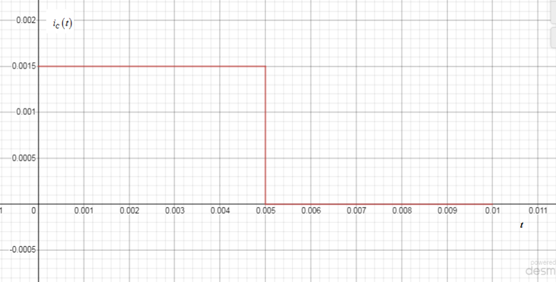
Figure 2
(c)
The current through the given element for the given voltage waveform.
To plot:
A graph of current through the element for
Answer to Problem 4.15HP
The current through the given element for the given voltage waveform is
A graph of current through the element for
Explanation of Solution
Given information:
Element is inductor and its value is
The given voltage waveform is shown below.
Calculation:
Consider the given graph for the voltage.
For
For
So, voltage can be written as
The given element is inductor. The current across it will be
Voltage
For
For
Current
A graph of current with respect to time is shown below.
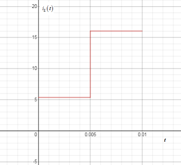
Figure 3
Want to see more full solutions like this?
Chapter 4 Solutions
Principles and Applications of Electrical Engineering


- R 2 0 5e-2 cos(31) 1 H Figure P4.48 If Vg (t) = 5e-2tcos(3t) V, and iL(0-)= -0.3A. a. determine the request voltages and currents. VR(0+)= VL(0+)= İL(0+)= b. On a single graph, draw to scale the waveforms of VG(t) and VL(t). c. expression for iL(t), t>0 urgent in one hour give like handwrittenarrow_forward3 Determine the voltage across the inductor in the circuit shown in Figure P4.63. 3 mH Vz(f) Vs(f) = 24 cos(1,000?) E wwarrow_forwardThe voltage v(t) shown in Figure P4.22 is appliedto a 10-mH inductor. Find the current through theinductor. Assume iL(0) = 0A.arrow_forward
- + M V1 Li L V2arrow_forwardFor the circuit shown in Figure (4.a): i) Find the voltage across the capacitor in polar form. ii) Draw the phasor diagram relationship of Vc and Vs. iii) Is this circuit pre-dominantly inductive or capacitive? Why?arrow_forwardThe voltage waveform shown in Figure P4.24appears across a 100-mH inductor and a 500-μFcapacitor. Plot the capacitor and inductor currents,iC(t) and iL(t), assuming iL(0) = 0A.arrow_forward
- For the circuit shown in Figure (4.a): i) a) Find the voltage across the capacitor in polar form. ii) Draw the phasor diagram relationship of Vc and Vs. iii) Is this circuit pre-dominantly inductive or capacitive? Why? R1=1kN X1 = 5000 Vs= 50 0 Xe = 5000 R2=1knarrow_forwarda. Show how you would connect all five capacitors to get a maximum capacitance and find the maximum capacitance in terms of C. b. Show how you would connect all five capacitors to get a minimum capacitance and find the minimum capacitance in terms of C.arrow_forwardThe initial voltage across the capacitor shown in Figure P4.3 is v C ( 0+ )=0. Find an expression for the voltage across the capacitor as a function of time, and sketch to scale versus timearrow_forward
- We know that the capacitor shown in Figure P4.11 is charged to a voltage of 10 V priorto t=0.a. Find expressions for the voltage across the capacitor vC(t) and the voltage across theresistor vR(t) for all time.b. Find an expression for the power delivered to the resistor.c. Integrate the power from t=0 to t=∞ to find the energy delivered.d. Show that the energy delivered to the resistor is equal to the energy stored in thecapacitor prior to t=0.arrow_forwardThree capacitors each of the capacitance C are given. The resultant capacitance 2/3 C Can be obtained by using them ? a)Two in parallel and third in series with this combination b)All in parallel c)All in series d)Two in series and third in parallel across this combinationarrow_forwardthe experiment for the picure below is a discarging capacitor experiment. the purpose of the experiment is to investigage discharging of capacitors using a resistor. if you are able to help me discuss my results on an experiment based on this picure please do so. many thanksarrow_forward
 Introductory Circuit Analysis (13th Edition)Electrical EngineeringISBN:9780133923605Author:Robert L. BoylestadPublisher:PEARSON
 Delmar's Standard Textbook Of ElectricityElectrical EngineeringISBN:9781337900348Author:Stephen L. HermanPublisher:Cengage Learning
 Programmable Logic ControllersElectrical EngineeringISBN:9780073373843Author:Frank D. PetruzellaPublisher:McGraw-Hill Education
 Fundamentals of Electric CircuitsElectrical EngineeringISBN:9780078028229Author:Charles K Alexander, Matthew SadikuPublisher:McGraw-Hill Education
 Electric Circuits. (11th Edition)Electrical EngineeringISBN:9780134746968Author:James W. Nilsson, Susan RiedelPublisher:PEARSON
 Engineering ElectromagneticsElectrical EngineeringISBN:9780078028151Author:Hayt, William H. (william Hart), Jr, BUCK, John A.Publisher:Mcgraw-hill Education,