
Concept explainers
Videos
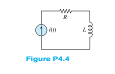
In the circuit shown in Figure P4.4, assume
Find:
a. The energy stored in the inductor for all time.
b. The energy delivered by the source for all time.
(a)
The energy stored in the inductor.
Answer to Problem 4.6HP
The energy stored in the inductor for different time interval is
Explanation of Solution
Calculation:
The given diagram is shown in Figure 1
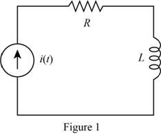
The expression for the energy stored in the conductor is given by,
Substitute
Substitute
Substitute
Substitute
The expression for the energy stored in the inductor for different time interval is given by,
Conclusion:
Therefore, the energy stored in the inductor for different time interval is
(b)
Theenergy delivered by the source.
Answer to Problem 4.6HP
The energy delivered by the source for various time interval is
Explanation of Solution
Calculation:
The expression for the energy stored in the conductor is given by,
Substitute,
Substitute,
The energy dissipated by the resistor from
Substitute
Solve further as,
Substitute
The expression for the power delivered by the source for
Substitute
The expression for the energy dissipated in the resistor from
Substitute
The expression for the energy delivered by the source for the time
Substitute
The energy delivered by the source for various time interval is given by,
Conclusion:
Therefore, the energy delivered by the source for various time interval is
Want to see more full solutions like this?
Chapter 4 Solutions
Principles and Applications of Electrical Engineering


- Q4: For the block diagram shown in figure (3). What is the value of K, and K₂ if: C(s) 0.1 C(s) 10K₂ & Also find the SNR 'N (s) 11s+6 R(S) 11s+1+10K₂ K₂ 10 S+1 (1) pop R() Figure (3) NO) K₁ S+1arrow_forward4. In the circuit shown in Figure P4, let Ri - 2Ω, R2 1Ω , R3 = 2Ω, R42Ω, Rs 1Ω, c=0.2F,L= 2H, ν(0) -3V, i(0) = 3A, vs(t) = 4 u(t), Vb = V. %3D %3D %3D %3D (a) Draw the circuit in the s-domain for t> 0. (b) Write a node equation at node a by summing the currents leaving node a. (c) Write a node equation at node b by summing the currents leaving node b. (d) Find Vo(s) in the s-domain. (e) Find vo(t) in the time domain. R1 Va R3 Vb i(0-) b a + R2 vs(t) R4 R5 Vo v (0-) Carrow_forwardQ4. Calculate the voltage, vo (t) of the circuit shown in Figure Q4 for t > 0 s.arrow_forward
- 4.14 Find a realization for (12s + 6) 22s + 23 3s + 34 Ĝ(s) 3s + 34arrow_forwardQ4/ Evaluate the state space expression for the below circuit if the output is the current through the resistor R1 (ir,). R2 ww ww İRI in i2 U(t) C :arrow_forwardA dc source is connected to a series RLC circuit by a switch that closes at t=0, as shownin Figure P4.61. The initial conditions are i(0+)=0 and vC(0+)=0. Write the differentialequation for vC(t).Solve for v C ( t ), if R = 20 Ω.arrow_forward
- Q4: Determine the step response ( c(t) ) of the control system shown in figure (4), then obtain the value of the error at 10 second R(s) C(s) error 1 s+4 Figure (4)arrow_forwardQ4. Consider the circuit of Figure Q4 with Is(t)= 3u(t) V, (a) Obtain VF(t) and i(t) for t>0 in the circuit (b) If Is(t) = 30u(t), determine VF(t) and i(t) for t>0 in the circuit (c) Compare the results (a) and (b). Explain and write the conclusion from the results (c). Is A 5Ω ww 5H M 292 Figure Q4 1Ω v(t) 20 (V) + 0.2Farrow_forward4.41. Find the z-transform of the following x[n): (a) x[n]= (b) x[n]=28[n+ 2]-38[n 2] (c) x[n]= 3- u[n]-2(3)"u[-n-1] 1. [-n-1] 4) (d) x[n]= 3 u[n]-2arrow_forward
- Q4: Sketch the root locus of the system, showing all steps in details K G(s)H(s) s4+ 5s3+8s2+6sarrow_forwardQ4/ Evaluate the state space expression for the below circuit if the output is the current through the resistor R1 (ir,). R1 ww R2 ww İRI it iz U(t) C1arrow_forwardneed laplace and solve in step by step i need clear ans by hand and solve very very fast in 20 min and thank you DYBALA SOLUTIONS OF DIFFERENTIAL EQUATIONS 4.83. Solve each of the following: (d) y(t) + y'(t) = t + 1arrow_forward
 Introductory Circuit Analysis (13th Edition)Electrical EngineeringISBN:9780133923605Author:Robert L. BoylestadPublisher:PEARSON
 Delmar's Standard Textbook Of ElectricityElectrical EngineeringISBN:9781337900348Author:Stephen L. HermanPublisher:Cengage Learning
 Programmable Logic ControllersElectrical EngineeringISBN:9780073373843Author:Frank D. PetruzellaPublisher:McGraw-Hill Education
 Fundamentals of Electric CircuitsElectrical EngineeringISBN:9780078028229Author:Charles K Alexander, Matthew SadikuPublisher:McGraw-Hill Education
 Electric Circuits. (11th Edition)Electrical EngineeringISBN:9780134746968Author:James W. Nilsson, Susan RiedelPublisher:PEARSON
 Engineering ElectromagneticsElectrical EngineeringISBN:9780078028151Author:Hayt, William H. (william Hart), Jr, BUCK, John A.Publisher:Mcgraw-hill Education,