
Mechanics of Materials
9th Edition
ISBN: 9780133254426
Author: Russell C. Hibbeler
Publisher: Prentice Hall
expand_more
expand_more
format_list_bulleted
Videos
Textbook Question
Chapter 5.4, Problem 5.51P
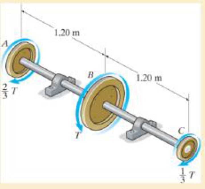
Determine the maximum allowable torque T. Also, find the corresponding angle of twist of disk A relative to disk C.
Expert Solution & Answer
Want to see the full answer?
Check out a sample textbook solution
Students have asked these similar questions
The pitch circle diameter of the smaller of the two spur wheels which mesh externally and haveinvolute teeth is 100 mm. The number of teeth are 16 and 32. The pressure angle is 20° and theaddendum is 0.32 of the circular pitch. Find the length of the path of contact of the pair of teeth.
The pinion (gear 2 on shaft a) rotates at 635 rev/min clockwise and transmits 1305 W through the idler pair (gears 3 and 4 on shaft b) to the output gear (gear 5 on shaft c). Gears
2 and 3 have a module of 2 mm, and gears 4 and 5 have a module of 3 mm. Pressure angles are all 20 degrees.
Solve for the magnitude of the force that shaft b must apply to gears 3 and 4 to maintain static equilibrium in the figure shown here. The figure is not to scale.
Please give your answer in units of newtons.
geard 615 verimin
m₂ = M₁ = 2mm
187
327
187
487
MG
M₁ = ₂ = 3mm
0=20°
I solved it and
дог 692.60 Х
សុំ
But fr is not correct
The pinion (gear 2 on shaft a) rotates at 635 rev/min clockwise and transmits 1305 W through the idler pair (gears 3 and 4 on shaft b) to the output gear (gear 5 on shaft c). Gears
2 and 3 have a module of 2 mm, and gears 4 and 5 have a module of 3 mm. Pressure angles are all 20 degrees.
Solve for the magnitude of the force that shaft b must apply to gears 3 and 4 to maintain static equilibrium in the figure shown here. The figure is not to scale.
187
327
487
Chapter 5 Solutions
Mechanics of Materials
Ch. 5.3 - Determine the internal torque at each section and...Ch. 5.3 - Determine the. internal torque at each section and...Ch. 5.3 - The solid and hollow shafts are each subjected to...Ch. 5.3 - The motor delivers 10 hp to the shaft. If it...Ch. 5.3 - The solid circular shaft is subjected to an...Ch. 5.3 - The hollow circular shaft is subjected to an...Ch. 5.3 - The shaft is hollow from A to B and solid from B...Ch. 5.3 - Determine the maximum shear stress in the...Ch. 5.3 - Determine the maximum shear stress in the shaft at...Ch. 5.3 - Determine the shear stress a: point A on the...
Ch. 5.3 - The solid 50-mm-diameter shaft is subjected to the...Ch. 5.3 - The gear motor can develop 3 hp when it turns at...Ch. 5.3 - The solid shaft of radius r is subjected to a...Ch. 5.3 - The solid shaft of radius r is subjected to a...Ch. 5.3 - 5-3. The solid shaft is fixed to the support at C...Ch. 5.3 - The copper pipe has an outer diameter of 40 mm and...Ch. 5.3 - The copper pipe has an outer diameter of 2.50 in....Ch. 5.3 - Prob. 5.6PCh. 5.3 - Prob. 5.7PCh. 5.3 - The solid 30-mm-diameter shaft is used to transmit...Ch. 5.3 - The solid shaft is fixed to the support at C and...Ch. 5.3 - Prob. 5.10PCh. 5.3 - The assembly consists of two sections of...Ch. 5.3 - Prob. 5.12PCh. 5.3 - 5-13. If The tubular shaft is made from material...Ch. 5.3 - A steel tube having an outer diameter of 2.5 in....Ch. 5.3 - Prob. 5.15PCh. 5.3 - Prob. 5.16PCh. 5.3 - The rod has a diameter of 1 in. and a weight of 10...Ch. 5.3 - The rod has a diameter of 1 in. and a weight of 15...Ch. 5.3 - 5-19. The shaft consists of solid 80-mm-diameter...Ch. 5.3 - Prob. 5.20PCh. 5.3 - 5-21. If the 40-mm-diameter rod is subjected to a...Ch. 5.3 - Prob. 5.22PCh. 5.3 - Prob. 5.23PCh. 5.3 - Prob. 5.24PCh. 5.3 - Prob. 5.25PCh. 5.3 - Prob. 5.26PCh. 5.3 - Prob. 5.27PCh. 5.3 - Prob. 5.28PCh. 5.3 - Prob. 5.29PCh. 5.3 - Prob. 5.30PCh. 5.3 - The solid steel shaft AC has a diameter of 25 mm...Ch. 5.3 - The pump operates using the motor that has a power...Ch. 5.3 - Prob. 5.33PCh. 5.3 - Prob. 5.34PCh. 5.3 - Prob. 5.35PCh. 5.3 - Prob. 5.36PCh. 5.3 - Prob. 5.37PCh. 5.3 - Prob. 5.38PCh. 5.3 - Prob. 5.39PCh. 5.3 - Prob. 5.40PCh. 5.3 - The A-36 steel tubular shaft is 2 m long and has...Ch. 5.3 - Prob. 5.42PCh. 5.3 - The solid shaft has a linear taper from rA at one...Ch. 5.3 - *5-44. The rod has a diameter of 0.5 in. and...Ch. 5.3 - 5-45. Solve Prob. 5-44 for the maximum torsional...Ch. 5.3 - A motor delivers 500 hp to the shaft, which is...Ch. 5.4 - The 60 mm-diameter steel shaft is subjected to the...Ch. 5.4 - Prob. 5.10FPCh. 5.4 - The hollow 6061-T6 aluminum shaft has an outer and...Ch. 5.4 - A series of gears are mounted on the...Ch. 5.4 - The 80-mm-diameter shaft is made of steel. If it...Ch. 5.4 - The 80-mm-diameter shaft is made of steel. If it...Ch. 5.4 - The propellers of a ship are connected to an A-36...Ch. 5.4 - Show that the maximum shear strain in the shaft is...Ch. 5.4 - 5-49. The A-36 steel axle is made from tubes AB...Ch. 5.4 - Prob. 5.50PCh. 5.4 - Determine the maximum allowable torque T. Also,...Ch. 5.4 - If the allowable shear stress is allow = 80 MPa,...Ch. 5.4 - Prob. 5.53PCh. 5.4 - If gear B supplies 15 kW of power, while gears A,...Ch. 5.4 - If the shaft is made of steel with the allowable...Ch. 5.4 - *5-56. The A-36 steel axle is made from tubes AB...Ch. 5.4 - If the rotation of the 100-mm-diameter A-36 steel...Ch. 5.4 - If the rotation of the 100-mm-diameter A-36 steel...Ch. 5.4 - It has a diameter of 1 in. and is supported by...Ch. 5.4 - Prob. 5.60PCh. 5.4 - Prob. 5.61PCh. 5.4 - Prob. 5.62PCh. 5.4 - Prob. 5.63PCh. 5.4 - Prob. 5.64PCh. 5.4 - Prob. 5.65PCh. 5.4 - When it is rotating at 80 rad/s. it transmits 32...Ch. 5.4 - It is required to transmit 35 kW of power from the...Ch. 5.4 - Prob. 5.68PCh. 5.4 - If a torque of T = 50 N m is applied to the bolt...Ch. 5.4 - If a torque of T= 50N m is applied to the bolt...Ch. 5.4 - Prob. 5.72PCh. 5.4 - If the shaft is subjected to a torque T at its...Ch. 5.4 - Prob. 5.74PCh. 5.4 - Prob. 5.75PCh. 5.4 - *5-76. A cylindrical spring consists of a rubber...Ch. 5.5 - Gst = 75 GPa.Ch. 5.5 - The A992 steel shaft has a diameter of 60 mm and...Ch. 5.5 - If the shaft is fixed at its ends A and B and...Ch. 5.5 - Prob. 5.80PCh. 5.5 - Prob. 5.81PCh. 5.5 - 5-82. The shaft is made from a solid steel section...Ch. 5.5 - 5-83. The motor A develops a torque at gear B of...Ch. 5.5 - If the allowable shear stresses for the magnesium...Ch. 5.5 - If a torque of T = 5 kNm is applied to end A,...Ch. 5.5 - Each has a diameter of 25 mm and they are...Ch. 5.5 - Each has a diameter of 25 mm and they are...Ch. 5.5 - It is fixed at its ends and subjected to a torque...Ch. 5.5 - 5–89. Determine the absolute maximum shear stress...Ch. 5.5 - The shaft is subjected to a torque of 800 lbft....Ch. 5.5 - Prob. 5.91PCh. 5.5 - The shaft is made of 2014-T6 aluminum alloy and is...Ch. 5.5 - The tapered shaft is confined by the fixed...Ch. 5.5 - Determine the reactions at the fixed supports A...Ch. 5.7 - 5-95. The aluminum rod has a square cross section...Ch. 5.7 - Prob. 5.96PCh. 5.7 - Prob. 5.97PCh. 5.7 - If it is subjected to the torsional loading,...Ch. 5.7 - Solve Prob.5-98 for the maximum shear stress...Ch. 5.7 - determine the maximum shear stress in the shaft....Ch. 5.7 - If the shaft has an equilateral triangle cross...Ch. 5.7 - 5-102. The aluminum strut is fixed between the two...Ch. 5.7 - is applied to the tube If the wall thickness is...Ch. 5.7 - If it is 2 m long, determine the maximum shear...Ch. 5.7 - Also, find the angle of twist of end B. The shaft...Ch. 5.7 - Also, find the corresponding angle of twist at end...Ch. 5.7 - If the solid shaft is made from red brass C83400...Ch. 5.7 - If the solid shaft is made from red brass C83400...Ch. 5.7 - The tube is 0.1 in. thick.Ch. 5.7 - 5-110. For a given maximum average shear stress,...Ch. 5.7 - 5-111. A torque T is applied to two tubes having...Ch. 5.7 - By what percentage is the torsional strength...Ch. 5.7 - 5-113. Determine the constant thickness of the...Ch. 5.7 - 5-114. Determine the torque T that can be applied...Ch. 5.7 - If the allowable shear stress is allow = 8 ksi,...Ch. 5.7 - *5-116. The tube is made of plastic, is 5 mm...Ch. 5.7 - 5–117. The mean dimensions of the cross section of...Ch. 5.7 - 5–118. The mean dimensions of the cross section of...Ch. 5.7 - If it is subjected to a torque of T = 40 Nm....Ch. 5.10 - If the transition between the cross sections has a...Ch. 5.10 - 5–121. The step shaft is to be designed to rotate...Ch. 5.10 - Prob. 5.122PCh. 5.10 - 5–123. The transition at the cross sections of the...Ch. 5.10 - *5–124. The steel used for the step shaft has an...Ch. 5.10 - 5–125. The step shaft is subjected to a torque of...Ch. 5.10 - Determine the radius of the elastic core produced...Ch. 5.10 - Assume that the material becomes fully plastic.Ch. 5.10 - diameter is subjected to a torque of 100 in.kip....Ch. 5.10 - Determine the torque T needed to form an elastic...Ch. 5.10 - Determine the torque applied to the shaft.Ch. 5.10 - 5–131. An 80-mm-diameter solid circular shaft is...Ch. 5.10 - Determine the ratio of the plastic torque Tp to...Ch. 5.10 - 5–133. If the step shaft is elastic-plastic as...Ch. 5.10 - 5–134. The solid shaft is made from an...Ch. 5.10 - 5–135. A 1.5-in.-diameter shaft is made from an...Ch. 5.10 - *5–136. The tubular shaft is made of a...Ch. 5.10 - 5–137. The shaft is made from a strain-hardening...Ch. 5.10 - 5–138. The tube is made of elastic-perfectly...Ch. 5.10 - Determine the torque required to cause a maximum...Ch. 5.10 - *5–140. The 2-m-long tube is made of an...Ch. 5.10 - is made from an elastic perfectly plastic material...Ch. 5.10 - 5–142. The 2-m-long lube is made from an...Ch. 5 - The shaft is made of A992 steel and has an...Ch. 5 - The shaft is made of A992 steel and has an...Ch. 5 - Determine the shear stress at the mean radius p =...Ch. 5 - If the thickness of its 2014-T6-aluminum skin is...Ch. 5 - Determine which shaft geometry will resist the...Ch. 5 - If couple forces P = 3 kip are applied to the...Ch. 5 - If the allowable shear stress for the aluminum is...Ch. 5 - Determine the angle of twist of its end A if it is...Ch. 5 - This motion is caused by the unequal belt tensions...
Knowledge Booster


Learn more about
Need a deep-dive on the concept behind this application? Look no further. Learn more about this topic, mechanical-engineering and related others by exploring similar questions and additional content below.Similar questions
- In the image on the right, there is a red gear G1 on the left with a radius of r1 = 2.81cm. Gear G1 is locked to the green gear G2 with a radius of r2 = 0.734cm. Gear G2 then shares the same axle as the blue circular saw G3, which has a radius of r3 known to make a full rotation every T = 0.836s. Using at least 6 significant digits in your calculations, compute the following: V3! 12.8cm. Gear G1 is W1 a) The angular speed wi of gear G1. Remember that angular speed is measured in radians per T3 r2 unit time. G2 b) The rim speed vi of gear G1. Since gears G1 and G2 are locked together, the rim speed of G2 is also v1. G1 G3 c) The angular speed w2 of gear G2. Since gear G2 and saw G3 share the same axle, the angular speed of G3 is also w2. d) The rim speed v3 of saw G3.arrow_forward5. The pitch circle diameter of the smaller of the two spur wheels which mesh externally and have involute teeth is 100 mm. The number of teeth are 16 and 32. The pressure angle is 20° and the addendum is 0.32 of the circular pitch. Find the length of the path of contact of the pair of teeth.arrow_forwarddetermine the number of revolutions done by Disk E at the same timearrow_forward
- A torque T = 0.30 N-m is applied to a bevel gear B. Bevel gear D meshes with gear B and drives pump A. Gear B has a radius of gyration of 150 mm and a weight of 50 N, whereas gear D and the im- peller of pump A have a combined radius of gy- ration of 50 mm and a weight of 100 N. Find how many revolutions of gear B are needed to get the pump up to 200 rpm from rest. What is the power output of the pump at this speed if it is 90% efficient.arrow_forwardIn the gear system shown, the motor applies a 190 lb-ft torque to the gear at A. A torque of Tc = 392 lb-ft is removed from the shaft at gear C, and the remaining torque is removed at gear D. Assume that DA-4-in.-diameter, Dg=12-in.-diameter, L₁=56 in., and L₂-30 in. Segments (1) and (2) are solid 1.5-in.-diameter steel [G = 12200 ksi] shafts, and the bearings shown allow free rotation of the shaft. Determine: (a) the maximum shear stresses T₁, T₂ in segments (1) and (2) of the shaft. (b) the rotation angle D/B of gear D relative to gear B. Answers: (a) T₁ (b) D/B = = i ᎠᏴ ; A DA i B L₁ Tc amala ksi, T₂ = L2 i Tp D ksi.arrow_forwardThe crossbar wrench is used to remove a lug nut from the automobile wheel. The mechanic applies a couple to the wrench such that his hands are a constant distance apart. Is it necessary that a b in order to produce the most effective turning of the nut? Explain. Also, what is the effect of changing the shaft dimension c in this regard? The forces act in the vertical plane. b. -F Farrow_forward
- Draw free-body diagrams of the two gears, assuming an input couple M on theOUT X shaft of the larger gear in the direction shown. Include forces at bearings A, B, D and E. M isthe reaction couple at the output shaft - i.e. the resistance to turning of the object being driven.The gears have 48 and 24 teeth respectively. If the input gear (large gear) turns at 100 rpm(= revolutions per minute), the output speed (small gear) is _______rpm.Wil OUT X IN Xl M be larger or smaller than M ?arrow_forwardThe two 1-kg gears A and B are attached to the ends of al 3-kg slender bar. The gears roll within the fixed ring gear C, which lies in the horizontal plane. (Figure 1) Figure 150 mm 400 mm- 150 mm Part A If a 10-N m torque is applied to the center of the bar as shown, determine the number of revolutions the bar must rotate starting from rest in order for it to have an angular velocity of WAB = 22 rad/s. For the calculation, assume the gears can be approximated by thin disks. Express your answer using three significant figures. ►View Available Hint(s) the number of revolutions = Submit Provide Feedback VAE vec ? Next >arrow_forwardFind the greatest and smallest values of the velocity ratio of two shafts joined with a universal coupling when the axes are at 60o to each other. Produce a graph of velocity ratio against angle for f to proof the calculated results.arrow_forward
- VA shaft have three eccentrics, each 75 mm diameter and 25 mm thick, machined in one piece with the shaft. The central planes of the eccentric are 60 mm apart. The distance of the centers from the axis of rotation are 12 mm, 18 mm and 12 mm and their angular positions are 120° apart. The density of metal is 7000 kg/m. Find the amount of out-of-balance force and couple at 600 rpm. If the shaft is balanced by adding two masses at a radius 75 mm and at distances of 100 mm from the central plane of the middle eccentric, find the amount of the masses and their angular positions.arrow_forwardThe turning-moment diagram for an engine consists of two isosceles triangles each with a height equivalent to a torque of 16kNm. The bases of the triangles lie between ? = 0 ? and ? = 180? , and ? = 180? and ? = 360? Sketch the turning-moment diagram and add the mean torque line. If the engine is to rotate with a mean speed of 130 rpm, calculate the following: the power developed the mass of the flywheel having a radius of gyration 1.1m to restrict the fluctuation of speed to +1.5% of the mean speed. Demonstrate which would be most effective to reduce the fluctuation of speed, a change in diameter of or a change in mass of the flywheel.arrow_forwardQ4:- Two shafts A and B in the same straight line are geared together through an intermediate parallel shaft C as shown in the Fig. below. The gears connecting A and C have a module of 2 mm, those connecting C and B have a module of 3.5 mm. The speed of B is to be about (0.1) that of A. If the two pinions have 24 teeth, find the most suitable number of teeth for the gears, the actual velocity ratio and the corresponding center distance. 2 3 4arrow_forward
arrow_back_ios
SEE MORE QUESTIONS
arrow_forward_ios
Recommended textbooks for you
 Elements Of ElectromagneticsMechanical EngineeringISBN:9780190698614Author:Sadiku, Matthew N. O.Publisher:Oxford University Press
 Mechanics of Materials (10th Edition)Mechanical EngineeringISBN:9780134319650Author:Russell C. HibbelerPublisher:PEARSON
 Thermodynamics: An Engineering ApproachMechanical EngineeringISBN:9781259822674Author:Yunus A. Cengel Dr., Michael A. BolesPublisher:McGraw-Hill Education
 Control Systems EngineeringMechanical EngineeringISBN:9781118170519Author:Norman S. NisePublisher:WILEY
 Mechanics of Materials (MindTap Course List)Mechanical EngineeringISBN:9781337093347Author:Barry J. Goodno, James M. GerePublisher:Cengage Learning
 Engineering Mechanics: StaticsMechanical EngineeringISBN:9781118807330Author:James L. Meriam, L. G. Kraige, J. N. BoltonPublisher:WILEY
Elements Of Electromagnetics
Mechanical Engineering
ISBN:9780190698614
Author:Sadiku, Matthew N. O.
Publisher:Oxford University Press
Mechanics of Materials (10th Edition)
Mechanical Engineering
ISBN:9780134319650
Author:Russell C. Hibbeler
Publisher:PEARSON
Thermodynamics: An Engineering Approach
Mechanical Engineering
ISBN:9781259822674
Author:Yunus A. Cengel Dr., Michael A. Boles
Publisher:McGraw-Hill Education
Control Systems Engineering
Mechanical Engineering
ISBN:9781118170519
Author:Norman S. Nise
Publisher:WILEY
Mechanics of Materials (MindTap Course List)
Mechanical Engineering
ISBN:9781337093347
Author:Barry J. Goodno, James M. Gere
Publisher:Cengage Learning
Engineering Mechanics: Statics
Mechanical Engineering
ISBN:9781118807330
Author:James L. Meriam, L. G. Kraige, J. N. Bolton
Publisher:WILEY
Understanding Failure Theories (Tresca, von Mises etc...); Author: The Efficient Engineer;https://www.youtube.com/watch?v=xkbQnBAOFEg;License: Standard youtube license