
Mechanics of Materials
9th Edition
ISBN: 9780133254426
Author: Russell C. Hibbeler
Publisher: Prentice Hall
expand_more
expand_more
format_list_bulleted
Concept explainers
Videos
Textbook Question
thumb_up100%
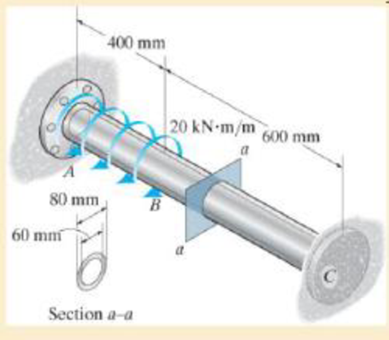
Chapter 5.5, Problem 5.92P
The shaft is made of 2014-T6 aluminum alloy and is fixed at A and C.
Expert Solution & Answer

Trending nowThis is a popular solution!

Students have asked these similar questions
A power transmission shaft is to carry a steady 30 horsepower while
rotating at 1000 rpm. Specify a suitable diameter for the solid circular shaft if it is to
be made from AISI 1020 cold-drawn steel. Use Appendix A-2 for preferred size.
Use the general shaft layout given and determine the critical diameters of the shaft
based on infinite fatigue life with a design factor of 1.5. Check for yielding. Check
the slopes at the bearings for satisfaction of the recommended limits in Table 7-2.
Assume that the deflections for the pulleys are not likely to be critical. The
material selected is 1050 Q and T. Given: Sut = 163 kpsi and Sy = 117 kpsi.
Use the following shaft layout assuming a gear transmits torque through a key and
keyseat at location A to another gear at location B.
16 in
14 in
F3
9 in
Gear A
20-in dia.
Gear B
8-in dia.
FA
300 lbf
20
A) Determine the location of the critical section on the shaft.
B) If the shaft's loading is fully reversed and the torque between
points A and B is constant, what are the values of the mean and alternating
torques and the mean and alternating moments in lbf-in?
A 9/16 inch height x 3.5 inches length flat key is keyed to a 50.8 mm diameter shaft. Determine the torque developed in key if bearing stress allowable is 35 Ksi. Use factor of safety of 3.
Chapter 5 Solutions
Mechanics of Materials
Ch. 5.3 - Determine the internal torque at each section and...Ch. 5.3 - Determine the. internal torque at each section and...Ch. 5.3 - The solid and hollow shafts are each subjected to...Ch. 5.3 - The motor delivers 10 hp to the shaft. If it...Ch. 5.3 - The solid circular shaft is subjected to an...Ch. 5.3 - The hollow circular shaft is subjected to an...Ch. 5.3 - The shaft is hollow from A to B and solid from B...Ch. 5.3 - Determine the maximum shear stress in the...Ch. 5.3 - Determine the maximum shear stress in the shaft at...Ch. 5.3 - Determine the shear stress a: point A on the...
Ch. 5.3 - The solid 50-mm-diameter shaft is subjected to the...Ch. 5.3 - The gear motor can develop 3 hp when it turns at...Ch. 5.3 - The solid shaft of radius r is subjected to a...Ch. 5.3 - The solid shaft of radius r is subjected to a...Ch. 5.3 - 5-3. The solid shaft is fixed to the support at C...Ch. 5.3 - The copper pipe has an outer diameter of 40 mm and...Ch. 5.3 - The copper pipe has an outer diameter of 2.50 in....Ch. 5.3 - Prob. 5.6PCh. 5.3 - Prob. 5.7PCh. 5.3 - The solid 30-mm-diameter shaft is used to transmit...Ch. 5.3 - The solid shaft is fixed to the support at C and...Ch. 5.3 - Prob. 5.10PCh. 5.3 - The assembly consists of two sections of...Ch. 5.3 - Prob. 5.12PCh. 5.3 - 5-13. If The tubular shaft is made from material...Ch. 5.3 - A steel tube having an outer diameter of 2.5 in....Ch. 5.3 - Prob. 5.15PCh. 5.3 - Prob. 5.16PCh. 5.3 - The rod has a diameter of 1 in. and a weight of 10...Ch. 5.3 - The rod has a diameter of 1 in. and a weight of 15...Ch. 5.3 - 5-19. The shaft consists of solid 80-mm-diameter...Ch. 5.3 - Prob. 5.20PCh. 5.3 - 5-21. If the 40-mm-diameter rod is subjected to a...Ch. 5.3 - Prob. 5.22PCh. 5.3 - Prob. 5.23PCh. 5.3 - Prob. 5.24PCh. 5.3 - Prob. 5.25PCh. 5.3 - Prob. 5.26PCh. 5.3 - Prob. 5.27PCh. 5.3 - Prob. 5.28PCh. 5.3 - Prob. 5.29PCh. 5.3 - Prob. 5.30PCh. 5.3 - The solid steel shaft AC has a diameter of 25 mm...Ch. 5.3 - The pump operates using the motor that has a power...Ch. 5.3 - Prob. 5.33PCh. 5.3 - Prob. 5.34PCh. 5.3 - Prob. 5.35PCh. 5.3 - Prob. 5.36PCh. 5.3 - Prob. 5.37PCh. 5.3 - Prob. 5.38PCh. 5.3 - Prob. 5.39PCh. 5.3 - Prob. 5.40PCh. 5.3 - The A-36 steel tubular shaft is 2 m long and has...Ch. 5.3 - Prob. 5.42PCh. 5.3 - The solid shaft has a linear taper from rA at one...Ch. 5.3 - *5-44. The rod has a diameter of 0.5 in. and...Ch. 5.3 - 5-45. Solve Prob. 5-44 for the maximum torsional...Ch. 5.3 - A motor delivers 500 hp to the shaft, which is...Ch. 5.4 - The 60 mm-diameter steel shaft is subjected to the...Ch. 5.4 - Prob. 5.10FPCh. 5.4 - The hollow 6061-T6 aluminum shaft has an outer and...Ch. 5.4 - A series of gears are mounted on the...Ch. 5.4 - The 80-mm-diameter shaft is made of steel. If it...Ch. 5.4 - The 80-mm-diameter shaft is made of steel. If it...Ch. 5.4 - The propellers of a ship are connected to an A-36...Ch. 5.4 - Show that the maximum shear strain in the shaft is...Ch. 5.4 - 5-49. The A-36 steel axle is made from tubes AB...Ch. 5.4 - Prob. 5.50PCh. 5.4 - Determine the maximum allowable torque T. Also,...Ch. 5.4 - If the allowable shear stress is allow = 80 MPa,...Ch. 5.4 - Prob. 5.53PCh. 5.4 - If gear B supplies 15 kW of power, while gears A,...Ch. 5.4 - If the shaft is made of steel with the allowable...Ch. 5.4 - *5-56. The A-36 steel axle is made from tubes AB...Ch. 5.4 - If the rotation of the 100-mm-diameter A-36 steel...Ch. 5.4 - If the rotation of the 100-mm-diameter A-36 steel...Ch. 5.4 - It has a diameter of 1 in. and is supported by...Ch. 5.4 - Prob. 5.60PCh. 5.4 - Prob. 5.61PCh. 5.4 - Prob. 5.62PCh. 5.4 - Prob. 5.63PCh. 5.4 - Prob. 5.64PCh. 5.4 - Prob. 5.65PCh. 5.4 - When it is rotating at 80 rad/s. it transmits 32...Ch. 5.4 - It is required to transmit 35 kW of power from the...Ch. 5.4 - Prob. 5.68PCh. 5.4 - If a torque of T = 50 N m is applied to the bolt...Ch. 5.4 - If a torque of T= 50N m is applied to the bolt...Ch. 5.4 - Prob. 5.72PCh. 5.4 - If the shaft is subjected to a torque T at its...Ch. 5.4 - Prob. 5.74PCh. 5.4 - Prob. 5.75PCh. 5.4 - *5-76. A cylindrical spring consists of a rubber...Ch. 5.5 - Gst = 75 GPa.Ch. 5.5 - The A992 steel shaft has a diameter of 60 mm and...Ch. 5.5 - If the shaft is fixed at its ends A and B and...Ch. 5.5 - Prob. 5.80PCh. 5.5 - Prob. 5.81PCh. 5.5 - 5-82. The shaft is made from a solid steel section...Ch. 5.5 - 5-83. The motor A develops a torque at gear B of...Ch. 5.5 - If the allowable shear stresses for the magnesium...Ch. 5.5 - If a torque of T = 5 kNm is applied to end A,...Ch. 5.5 - Each has a diameter of 25 mm and they are...Ch. 5.5 - Each has a diameter of 25 mm and they are...Ch. 5.5 - It is fixed at its ends and subjected to a torque...Ch. 5.5 - 5–89. Determine the absolute maximum shear stress...Ch. 5.5 - The shaft is subjected to a torque of 800 lbft....Ch. 5.5 - Prob. 5.91PCh. 5.5 - The shaft is made of 2014-T6 aluminum alloy and is...Ch. 5.5 - The tapered shaft is confined by the fixed...Ch. 5.5 - Determine the reactions at the fixed supports A...Ch. 5.7 - 5-95. The aluminum rod has a square cross section...Ch. 5.7 - Prob. 5.96PCh. 5.7 - Prob. 5.97PCh. 5.7 - If it is subjected to the torsional loading,...Ch. 5.7 - Solve Prob.5-98 for the maximum shear stress...Ch. 5.7 - determine the maximum shear stress in the shaft....Ch. 5.7 - If the shaft has an equilateral triangle cross...Ch. 5.7 - 5-102. The aluminum strut is fixed between the two...Ch. 5.7 - is applied to the tube If the wall thickness is...Ch. 5.7 - If it is 2 m long, determine the maximum shear...Ch. 5.7 - Also, find the angle of twist of end B. The shaft...Ch. 5.7 - Also, find the corresponding angle of twist at end...Ch. 5.7 - If the solid shaft is made from red brass C83400...Ch. 5.7 - If the solid shaft is made from red brass C83400...Ch. 5.7 - The tube is 0.1 in. thick.Ch. 5.7 - 5-110. For a given maximum average shear stress,...Ch. 5.7 - 5-111. A torque T is applied to two tubes having...Ch. 5.7 - By what percentage is the torsional strength...Ch. 5.7 - 5-113. Determine the constant thickness of the...Ch. 5.7 - 5-114. Determine the torque T that can be applied...Ch. 5.7 - If the allowable shear stress is allow = 8 ksi,...Ch. 5.7 - *5-116. The tube is made of plastic, is 5 mm...Ch. 5.7 - 5–117. The mean dimensions of the cross section of...Ch. 5.7 - 5–118. The mean dimensions of the cross section of...Ch. 5.7 - If it is subjected to a torque of T = 40 Nm....Ch. 5.10 - If the transition between the cross sections has a...Ch. 5.10 - 5–121. The step shaft is to be designed to rotate...Ch. 5.10 - Prob. 5.122PCh. 5.10 - 5–123. The transition at the cross sections of the...Ch. 5.10 - *5–124. The steel used for the step shaft has an...Ch. 5.10 - 5–125. The step shaft is subjected to a torque of...Ch. 5.10 - Determine the radius of the elastic core produced...Ch. 5.10 - Assume that the material becomes fully plastic.Ch. 5.10 - diameter is subjected to a torque of 100 in.kip....Ch. 5.10 - Determine the torque T needed to form an elastic...Ch. 5.10 - Determine the torque applied to the shaft.Ch. 5.10 - 5–131. An 80-mm-diameter solid circular shaft is...Ch. 5.10 - Determine the ratio of the plastic torque Tp to...Ch. 5.10 - 5–133. If the step shaft is elastic-plastic as...Ch. 5.10 - 5–134. The solid shaft is made from an...Ch. 5.10 - 5–135. A 1.5-in.-diameter shaft is made from an...Ch. 5.10 - *5–136. The tubular shaft is made of a...Ch. 5.10 - 5–137. The shaft is made from a strain-hardening...Ch. 5.10 - 5–138. The tube is made of elastic-perfectly...Ch. 5.10 - Determine the torque required to cause a maximum...Ch. 5.10 - *5–140. The 2-m-long tube is made of an...Ch. 5.10 - is made from an elastic perfectly plastic material...Ch. 5.10 - 5–142. The 2-m-long lube is made from an...Ch. 5 - The shaft is made of A992 steel and has an...Ch. 5 - The shaft is made of A992 steel and has an...Ch. 5 - Determine the shear stress at the mean radius p =...Ch. 5 - If the thickness of its 2014-T6-aluminum skin is...Ch. 5 - Determine which shaft geometry will resist the...Ch. 5 - If couple forces P = 3 kip are applied to the...Ch. 5 - If the allowable shear stress for the aluminum is...Ch. 5 - Determine the angle of twist of its end A if it is...Ch. 5 - This motion is caused by the unequal belt tensions...
Knowledge Booster


Learn more about
Need a deep-dive on the concept behind this application? Look no further. Learn more about this topic, mechanical-engineering and related others by exploring similar questions and additional content below.Similar questions
- What would be the recommend torque and max torque for a hollow shaft made of 52100 bearing steel equivalent, that is M30x3.5-6H, threaded on one end. Length is 952 mm. Shaft diameter is 40 mm, inner diameter of 20 mm. Screwing into an aluminum 7075- t7351, plate that is 1 inch thick. The shaft would carry a load of 138 lbs, evenly distributed.arrow_forwardHW11 The approximate distance between the two parallel shafts is 600 mm. The shafts are to be connected by spur gearing. If one shaft runs at 1000 r.p.m. and the other at 2500 r.p.m., find the number of teeth on each wheel, if the module is 12 mm. Also, determine the exact distance apart from the shafts.arrow_forwardThe axial load carrying capacity of angular contact ball bearings will with increasing contact angle. Select one: O a. Constant Ob. Decreases Increases O d. Fluctuating iparrow_forward
- Use the general shaft layout given and determine critical diameters of the shaft based on infinite fatigue life with a design factor of 1.5. Check for yielding. Check the slopes at the bearings for satisfaction of the recommended limits in Table 7-2. Assume that the deflections for the pulleys are not likely to be critical. 10 in 500 lbf 75 lbf 8-in dia. Bearing at O 10.0" 500 lb d 75 lb Material 1040 Q and T 18 in Use the following shaft layout assuming a pulley transmits torque through a key and keyseat at location A to another pulley at location B. Assume the tensions in the belt at pulley Bare T₁ and T2, where T₁ is 15% of T2. NOTE: This is a multi-part question. Once an answer is submitted, you will be unable to return to this part. 10-in dia. 12 in T₂ 8.0⁰ T₁ 18.0" 10.0" I B pulley diameter = 8.0" Sut 113 kpsi T2 T1 pulley diameter = 10.0" Sy 86 kpsi 12.0" Bearing at C Using the DE-Goodman criteria and a design factor of 1.5, calculate the diameter based on the shaft's loadings…arrow_forwardUse the general shaft layout given and determine critical diameters of the shaft based on infinite fatigue life with a design factor of 1.5. Check for yielding. Check the slopes at the bearings for satisfaction of the recommended limits in Table 7-2. Assume that the deflections for the pulleys are not likely to be critical. 500 lbf 75 lbf 8-in dia. Bearing at O 500 lb d 10.0" 75 lb Material 1040 Q and T 18 in Use the following shaft layout assuming a pulley transmits torque through a key and keyseat at location A to another pulley at location B. Assume the tensions in the belt at pulley B are T₁ and T2, where T₁ is 15% of T2. NOTE: This is a multi-part question. Once an answer is submitted, you will be unable to return to this part. 10-in dia. 12 in T₂ T₁ The mean torque is 0 lb-in. The alternating torque is 2125 lb-in. The mean moment is 0 lb-in. The alternating moment is 5000 lb-in. 18.0" pulley diameter = 8.0" Sut 113 kpsi 10.0 B T2 T1 pulley diameter = 10.0" Sy 86 kpsi 12.0"…arrow_forwardThe unit for torsional rigidity of a shaft is N/m2 Select one: True Falsearrow_forward
- Design the size of a solid shaft for a 500 hp, 250 rpm if the allowable torsional deflection is 1 degree. Use C1045 as rolled steel for medium shock loading.arrow_forwardWhat would be the recommend torque and max torque for a hollow shaft made of 52100 bearing steel equivalent, that is M30x3.5-6H, threaded on one end. Length is 952 mm. Shaft diameter is 40 mm. Screwing into an aluminum 7075- t7351, plate that is 1 inch thick.arrow_forwardTikrit Uni. Eng. College Mech. Eng Class : 3D Machine Design 1" term 2nd month Exam Sat 22-1-2021 75Min Q1 The rotating solid steel shaft is simply supported by bearings A and B, the gear has 500-mm pitch diameter. The shaft transmits a torque, T. The shaft is machined from steel AISI 1040 CD. Using a factor of safety of 2.5, determine a- The torque T b- Reactions RA and Rc c- Draw th Bending Diagram d- Maximum bending moment e- the minimum allowable diameter of the shaft using DE_Goodman theory. Assume sharp fillet radii at the bearing shoulders. 450 mm 550 mm C 500-mm dia. Fy = 8000 Narrow_forward
- Q2-a) determine the advantages of power screw. h b-A shaft is to transmit 50 KW at 1200 rpm.. The allowable shear stress of the shaft material is 60N/mm².Design a suitable ball bearing to support this shaft.(use bearing tables)arrow_forwardConsider the belt drive having a diameter of 150 mm that is mounted on the overhung end of ashaft, 30 mm from the nearest bearing. The stepped shaft is made of steel having Su = 965 MPa(140 ksi). The shaft diameter, d, is 30 mm. The bearing bore, D, is 36 mm. The fillet with amachined surface has a radius, r, of 3 mm. What is the safety factor with respect to eventualfatigue failure of the shaft?arrow_forwardthick lnange be! The total torque required to turn the double threaded power screw is 55 N.m. If the screw turns at 285 rpm and the pitch of 4mm, find: A. The horsepower input of the power screw. B. The efficiency if the weight loaded is 10 kN.arrow_forward
arrow_back_ios
SEE MORE QUESTIONS
arrow_forward_ios
Recommended textbooks for you
 Elements Of ElectromagneticsMechanical EngineeringISBN:9780190698614Author:Sadiku, Matthew N. O.Publisher:Oxford University Press
 Mechanics of Materials (10th Edition)Mechanical EngineeringISBN:9780134319650Author:Russell C. HibbelerPublisher:PEARSON
 Thermodynamics: An Engineering ApproachMechanical EngineeringISBN:9781259822674Author:Yunus A. Cengel Dr., Michael A. BolesPublisher:McGraw-Hill Education
 Control Systems EngineeringMechanical EngineeringISBN:9781118170519Author:Norman S. NisePublisher:WILEY
 Mechanics of Materials (MindTap Course List)Mechanical EngineeringISBN:9781337093347Author:Barry J. Goodno, James M. GerePublisher:Cengage Learning
 Engineering Mechanics: StaticsMechanical EngineeringISBN:9781118807330Author:James L. Meriam, L. G. Kraige, J. N. BoltonPublisher:WILEY
Elements Of Electromagnetics
Mechanical Engineering
ISBN:9780190698614
Author:Sadiku, Matthew N. O.
Publisher:Oxford University Press
Mechanics of Materials (10th Edition)
Mechanical Engineering
ISBN:9780134319650
Author:Russell C. Hibbeler
Publisher:PEARSON
Thermodynamics: An Engineering Approach
Mechanical Engineering
ISBN:9781259822674
Author:Yunus A. Cengel Dr., Michael A. Boles
Publisher:McGraw-Hill Education
Control Systems Engineering
Mechanical Engineering
ISBN:9781118170519
Author:Norman S. Nise
Publisher:WILEY
Mechanics of Materials (MindTap Course List)
Mechanical Engineering
ISBN:9781337093347
Author:Barry J. Goodno, James M. Gere
Publisher:Cengage Learning
Engineering Mechanics: Statics
Mechanical Engineering
ISBN:9781118807330
Author:James L. Meriam, L. G. Kraige, J. N. Bolton
Publisher:WILEY
Understanding Torsion; Author: The Efficient Engineer;https://www.youtube.com/watch?v=1YTKedLQOa0;License: Standard YouTube License, CC-BY