
Videos
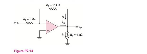
(a) The input to the circuit shown in Figure P9.14 is
(a)
The value of the output voltage
Answer to Problem 9.14P
The value of the voltage
Explanation of Solution
Calculation:
The given diagram is shown in Figure 1
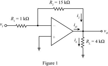
Apply KCL at the inverting terminal.
Substitute
The expression for the value of the current
Substitute
The expression for the value of the current
Substitute
The expression for the value of the current
Substitute
Conclusion:
Therefore, the value of the voltage
(b)
The value of the output voltage
Answer to Problem 9.14P
The value of the voltage
Explanation of Solution
Calculation:
The expression for the output voltage is given by,
Substitute
The expression for the value of the current
Substitute
The expression for the value of the current
Substitute
The conversion from
The conversion from
The conversion from
The expression for the value of the current
Substitute
Conclusion:
Therefore, the value of the voltage
(c)
The value of the output voltage
Answer to Problem 9.14P
The value of the voltage
Explanation of Solution
Calculation:
The conversion from
The conversion from
The expression for the output voltage is given by,
Substitute
The expression for the value of the current
Substitute
The expression for the value of the current
Substitute
The expression for the value of the current
Substitute
Conclusion:
Therefore, the value of the voltage
Want to see more full solutions like this?
Chapter 9 Solutions
Microelectronics: Circuit Analysis and Design


- For the circuit below with input voltage V1, a step function of magnitude 25 volts at time t-0, find the transient response voltage across the capacitor C1 and plot the results: (Provide your calculations and reasoning for your answer.) R1 555 250mH V1 = 0 V2 - 25 TD = 0 TR In V1 C1 TF in PW- 25 PER = 3.3uarrow_forwardQ/ The step response of the system shown in figure (7) isim d fett # dt I delay to ght) 1arrow_forwardR₁ ww VIO- Figure P9.28 *9.28 The circuit in Figure P9.28 is similar to the inverting amplifier except the resistor R3 has been added. (a) Derive the expression for vo in terms of vj and the resistors. (b) Derive the expression for i3 in terms of u and the resistors. +10 V R₂ R₂ 50 ΚΩ Potentiometer R4 = 10 ΚΩ R₂ ww R₁ = 1 ks2 -OVO iz -00 RL > R3 = 10092 Figure P9.29 *D9.29 Design the amplifier in Figure P9.29 such that the output voltage varies be- tween ±10 V as the wiper arm of the potentiometer changes from -10 V to +10 V. What is the purpose of including R3 and R4 instead of connecting R₁ directly to the wiper arm? -10 Varrow_forward
- 0 Consider the image below. Derive an expression for E as a function of the excitation voltage E¡ and the resistances R₁ and R₂. You may have to use Ohm's law and/or Kirchhoff's laws. Ei allt R1 Eo 0 R2arrow_forwardThe ratio of the forward voltage to the forward current is called the characteristic impedance? What is forward voltage? What is the forward current? What is characteristic impedance?arrow_forwardA series circuit consists of a resistor, a coil, and a capacitorconnected across a 300V, 60Hz AC source. The current drawn is 20A.The voltage across the resistor is 60V, that across the coil is 260V andthat across the capacitor is 100V. The resultant voltage across the coiland the capacitor is 254.56V. Determine (a) the resistance of theresistor, (b) the resistance and inductance of the coil, and (c) theresistance and capacitance of the capacitor.arrow_forward
- Consider the series R-L circuit shown in figure below. For obtaining transient free response, switch should be closed at instant t = to. Find the value of to. (consider R = wL) t=to 2sin 8t R vor Larrow_forwardConsider the series R-L circuit shown in figure below. For obtaining transient free response, switch should be closed at instant t = to. Find the value of to. (consider R = wL) t=to 2sin 8t vor RLarrow_forwardA series R-L-C circuit is connected to a 0.2 V supply and the current is at its maximum value of 4 mA when the supply frequency is adjusted to 3 kHz. The Q-factor of the circuit under these conditions is 100. Determine the value of (a) the circuit resistance, (b) the circuit inductance, (c) the circuit capacitance and (d) the voltage across the capacitor. ANS: (a) 50 2; (b) 0.265 H; (c) 10.61 nF; (d) 20 V.arrow_forward
- 4) The function sin x (which you may remember from Calculus 1 limits) is important in signal processing and electrical engineering, and is known as the "sinc" function, often abbreviated as just sinc(x). Find § sinc(x) dx. Then, approximate ſ sinc(x) dx using the first five terms of the appropriate series.arrow_forwardWrite the state equations for the circuit given in Figure. RF12 R=22 RF32 + Vc L v=Bi e +1arrow_forwardAnswer the following with illustration and solution. 1.) A circuit consisting of a resistor of 5kohms in series with a capacitor of 10 nanofarad is connected across a 16v sinusoidal supply. Calculate the output voltage at a frequency of 60Hz and again at frequency of 120Hz. This is the example/guide that might help.arrow_forward
 Introductory Circuit Analysis (13th Edition)Electrical EngineeringISBN:9780133923605Author:Robert L. BoylestadPublisher:PEARSON
 Delmar's Standard Textbook Of ElectricityElectrical EngineeringISBN:9781337900348Author:Stephen L. HermanPublisher:Cengage Learning
 Programmable Logic ControllersElectrical EngineeringISBN:9780073373843Author:Frank D. PetruzellaPublisher:McGraw-Hill Education
 Fundamentals of Electric CircuitsElectrical EngineeringISBN:9780078028229Author:Charles K Alexander, Matthew SadikuPublisher:McGraw-Hill Education
 Electric Circuits. (11th Edition)Electrical EngineeringISBN:9780134746968Author:James W. Nilsson, Susan RiedelPublisher:PEARSON
 Engineering ElectromagneticsElectrical EngineeringISBN:9780078028151Author:Hayt, William H. (william Hart), Jr, BUCK, John A.Publisher:Mcgraw-hill Education,