
Concept explainers
Videos
For the beam and loading shown, determine (a) the equation of the elastic curve, (b) the deflection at point B, (c) the deflection at point D.
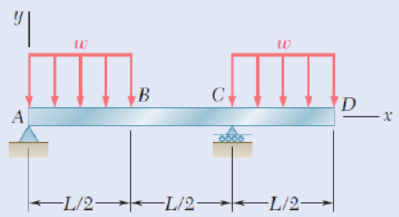
Fig. P9.44
(a)
Find the equation of the elastic curve.
Answer to Problem 44P
The equation of the elastic curve is,
Explanation of Solution
Show the free-body diagram of the beam AD as in Figure 1.
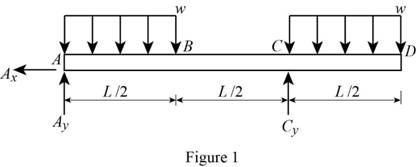
Determine the vertical reaction at point C by taking moment about point A.
Write the singularity equation for load intensity as follows;
Integrate the equation to find the shear force.
By definition, the change in bending moment with respect to change in distance is shear force. It is expressed as follows:
Integrate the equation to find the bending moment.
Write the second order differential equation as follows;
Here, the moment at the corresponding section is
Substitute
Integrate the equation with respect to x;
Integrate the Equation (2) with respect to x.
Boundary condition 1:
At the point D;
Substitute
Boundary condition 2:
At the point A;
Substitute
Boundary condition 3:
At the point C;
Substitute
Substitute
Therefore, the equation of the elastic curve is
(b)
Find the deflection at point B of the beam.
Answer to Problem 44P
The deflection at mid-point B of the beam is
Explanation of Solution
Refer to part (a);
Refer to Equation (4);
At point B;
Substitute
Therefore, the deflection at point B of the beam is
(c)
Find the deflection at point D of the beam.
Answer to Problem 44P
The deflection at mid-point D of the beam is
Explanation of Solution
Refer to part (a); Equation (4);
At point D;
Substitute
Therefore, the deflection at point D of the beam is
Want to see more full solutions like this?
Chapter 9 Solutions
Mechanics of Materials, 7th Edition


- Determine the slope and deflection at D for the beam and loading shown (Fig. 8.33), knowing that the flexural rigidity of the beam is EI = 100 MN m². A 150 kN 2 m D Fig. 8.33 20 kN/m -8 m- Barrow_forwardDetermine (i) the maximum deflection of the beam (ii) the location of maximum deflection Where; L = 1 P = 33N | = 3.3 x 108 mm4 E = 200 GPaarrow_forwardFor the beam and loading shown, determine (a) the equation of the elastic curve, (b) the slope at end A, (c) the deflection at the midpoint of the span. 司 x2 w = 4wo - L² В Aarrow_forward
- PROBLEM 9.11 Mo (a) Determine the location and magnitude of the maximum deflection of beam AB. (b) Assuming that beam AB is a W360 x 64, L = 3.5 m, and E = 200 GPa, calculate the maximum allowable value of the applied moment Mo if the maximum deflection is not to excecd I mm. Mo = 45.3 kN · m %3Darrow_forwardFor the beam and loading shown, use the double-integration method to determine (a) the equation of the elastic curve for the beam, (b) the location of the maximum deflection, and (c) the maximum beam deflection. Assume that El is constant for the beam. Let w = 13 kN/m, L = 4.0 m, E = 180 GPa, and I = 130 x 106 mm“. B L Answer: (b) х %3 m (c) Vmax mmarrow_forwardFig. P9.78 E 9.79 and 9.80 For the uniform beam shown, determine (a) the reaction at A, (b) the reaction at B. ***** A Fig. P9.80 -L/2- Answer (a) 7 wL/128 1. (b)57 wL/128 1:9wL2/128. C -L/2- Barrow_forward
- b. Determine the deflection of the beam at midpoint for the beam loading system shown in the figure given below : Take : E = 200 GN/m2 and I = 83 x 106 m. 20 N 30 N 10 N/m 10 m 5 m 10 m Fig. 10.arrow_forwardQ.4) Determine the deflection of the beam at point C. 7.arrow_forwardPROBLEM 9.9 Knowing that beam AB is a W130× 23.8 rolled shape and that L P=50 kN, L=1.25 m, and E = 200 GPa, determine (a) the slope at A, (b) the deflection at C. L/2 L/2 [x=0, y=0] [x = L, y=0] L dy 2' dx e = 2.77x10³ rad Yc = 1.156 mm.arrow_forward
- For the beam and loading shown, determine (a) the equation of the elastic curve, (b) the deflection at the free end.arrow_forwardProblem 2. (a) Draw the moment diagram for the beam. (b) Observing the direction of load and sign of the moment diagram, and knowledge of the boundary conditions, sketch the elastic curve, that is, the vertical deflection of the axial line thru the centroid of the beam section, (c) Using integration, determine the equation of the elastic curve for the beam using the x coordinate that is valid for 0 < x < L/2. (d) Specify the slope at A and the beam's maximum deflection. El is constant. For parts (a) and (b), model only one-half of the beam, from x=0 to x=L/2, and use the symmetry dv boundary condition, slope = 0, at the vertical line of symmetry at x=L/2. dx X NA Barrow_forwardQUESTION 1. The simply supported beam in Fig. 1 supports a concentrated load of 300 N as shown. Using El = 20.48 x 10³ Nm², determine (a) the slope angle of the elastic curve at A, and (b) the displacement at D. R₁ = 100 N 1.0 m D 2m Fig. 1 300 N B 1.0 m- X |RC= 200 Narrow_forward
 Elements Of ElectromagneticsMechanical EngineeringISBN:9780190698614Author:Sadiku, Matthew N. O.Publisher:Oxford University Press
 Mechanics of Materials (10th Edition)Mechanical EngineeringISBN:9780134319650Author:Russell C. HibbelerPublisher:PEARSON
 Thermodynamics: An Engineering ApproachMechanical EngineeringISBN:9781259822674Author:Yunus A. Cengel Dr., Michael A. BolesPublisher:McGraw-Hill Education
 Control Systems EngineeringMechanical EngineeringISBN:9781118170519Author:Norman S. NisePublisher:WILEY
 Mechanics of Materials (MindTap Course List)Mechanical EngineeringISBN:9781337093347Author:Barry J. Goodno, James M. GerePublisher:Cengage Learning
 Engineering Mechanics: StaticsMechanical EngineeringISBN:9781118807330Author:James L. Meriam, L. G. Kraige, J. N. BoltonPublisher:WILEY