
Concept explainers
Videos
Two cover plates are welded to the rolled-steel beam as shown. Using E = 29 × 106 psi, determine (a) the slope at end C, (b) the deflection at end C.
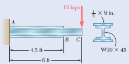
Fig. P9.108
(a)
Find the slope
Answer to Problem 108P
The slope
Explanation of Solution
Given information:
The elastic modulus (E) is
The section of the beam is
The dimension of the top plate and bottom plate is
Calculation:
Refer Appendix C, “Properties of Rolled steel shapes”.
The moment of inertia (I) for the given section is
The depth of the section (D) is
The width of the section (b) is
Use moment area method:
Consider from bottom.
Calculate the neutral axis
Substitute
Top plate:
Calculate the area of the top plate
Since the dimension of the top plate is
Calculate the depth of neutral axis (d) using the formula:
Substitute
Calculate the product of
Substitute
Calculate the moment of inertia (I) using the formula:
Here, b is the width the top plate and h is the height of the top plate.
Substitute
Bottom plate:
Top plate:
Calculate the area of the bottom plate
Since the dimension of the bottom plate is
Calculate the depth of neutral axis (d) using the formula:
Substitute
Calculate the product of
Substitute
Calculate the moment of inertia (I) using the formula:
Here, b is the width the top plate and h is the height of the top plate.
Substitute
Tabulate the calculated values and compute the moment of inertia (I) as in Table (1).
| Segments | Area, A | Depth, d (in.) | ||
| Top plate | 4.5 | 5.3 | 126.405 | 0.09375 |
| 248 | ||||
| Bottom plate | 4.5 | 5.3 | 126.405 | 0.09375 |
| Summation | 252.81 | 248 |
Take the greater value of moment of inertia from the three segments is
Calculate the moment of inertia (I) using the relation:
Substitute
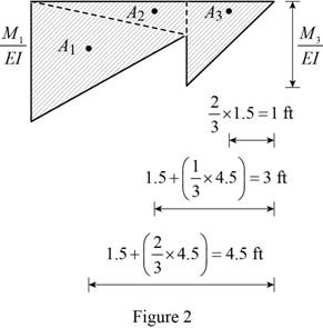
Show the free body diagram of beam by considering the point load as in Figure 1.
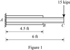
Draw the moment diagram of the above beam as in Figure 2.
Calculate the moment
Calculate the ratio of
Substitute
Calculate the area
Here,
Substitute 4.5 ft for
Calculate the area
Substitute
Calculate the moment
Calculate the ratio of
Substitute
Calculate the area
Here,
Substitute 1.5 m for
Show the tangent slope and deflection at point C related to reference tangent as in Figure 3.
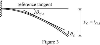
Since the support A has fixed support, the slope
Calculate the slope at the end C related to the fixed end A
Substitute
Calculate the slope at the point C
Substitute 0 for
Thus, the slope
(b)
Find the deflection
Answer to Problem 108P
The deflection
Explanation of Solution
Given information:
The elastic modulus (E) is
The section of the beam is
The dimension of the top plate and bottom plate is
Calculation:
Calculate the deflection at end C related to the fixed end A
Substitute
Calculate the deflection at the point C
Substitute 0 for
Thus, the deflection
Want to see more full solutions like this?
Chapter 9 Solutions
Mechanics of Materials, 7th Edition


- PROBLEM 9.15 Mg= 60 kN m For the beam and loading shown, determine the deflection at point C. Use E = 200 GPa. W200 x 35.9 a- 1.2 m -L = 4.8 m Ус = 6.28 mm T 1 %3Darrow_forwardFor the beam and loading shown, determine (a) the slope at end A, (b) the deflection at point C. Use E= 200 GPaarrow_forwardThe two beams shown have the same cross section and are joined by a hinge at C. For the loading shown, determine (a) the slope at point A, (b) the deflection at point B. Use E=29 *106 psiarrow_forward
- 3.2 kN 300 mm B 75 mm A 9.77 The steel bars BE and AD each have a 6 × 18-mm cross section. Knowing that E = 200 GPa, determine the deflections of points A, B, and C of the rigid bar ABC. 400 mm-+400 mm Fig. P9.77arrow_forwardPROBLEM 9.9 Knowing that beam AB is a W130x23.8 rolled shape and that L P=50 kN, L=1.25 m, and E = 200 GPa, determine (a) the slope at A, (b) the deflection at C. W -L/2 L/2 [x=0, y=0] [x= L, y=0] L dy 2' dx O = 2.77x10³ rad Yc = 1.156 mm,arrow_forwardDetermine the slope and deflection at D for the beam and loading shown (Fig. 8.33), knowing that the flexural rigidity of the beam is EI = 100 MN m². A 150 kN 2 m D Fig. 8.33 20 kN/m -8 m- Barrow_forward
- A 7/8-in.-diameter rod BC is attached to the lever AB and to the fixed support at C. Lever AB has a uniform cross section 38 in. thick and 1 in. deep. For the loading shown, determine the deflection of point A. Use E=29 *106 psi and G=11.2 *106 psi.arrow_forwardFor the cantilever beam and loading shown, determine the slope and deflection at point B. Use E = 27 × 106 15 1b/in. -30 in. The slope at end Bis B 125 lb 10 in. The deflection at end Bis 1.75 in. H X 10 rad. in. ↓ psi.arrow_forwardPROBLEM 9.11 Mg (a) Determine the location and magnitude of the maximum deflection of * beam AB. (b) Assuming that beam AB is a W360 x 64, L = 3.5 m, and E = 200 GPa, calculate the maximum allowable value of the applied moment M, if the maximum deflection is not to exceed 1 mm. B = 45.3 kN · marrow_forward
- An overhang beam with negligible weight is loaded as shown. Knowing that the flexural rigidity of the beam is El = 2 × 10⁵ kNm², (a) Reactions at A and B (a) determine the reactions at supports A and B, (b) derive the elastic (b) section AB curve for section AB, (c) derive the elastic curve for section BC, and v = (d) determine the deflection at point C. v = (c) section BC v' = 2 kN/m v = (d) m marrow_forwardDetermine (i) the maximum deflection of the beam (ii) the location of maximum deflection Where; L = 1 P = 33N | = 3.3 x 108 mm4 E = 200 GPaarrow_forwardEach of the links AB and CD is made of aluminum and has a cross-sectional area of 0.2 sq.in. Knowing that they support the rigid member BC, determine the downward deflection (in inches) of point C. if x = 13.7 in, y = 28.1 in, z = 20 in, E = 10754407 psi, and P = 26 kips.arrow_forward
 Elements Of ElectromagneticsMechanical EngineeringISBN:9780190698614Author:Sadiku, Matthew N. O.Publisher:Oxford University Press
 Mechanics of Materials (10th Edition)Mechanical EngineeringISBN:9780134319650Author:Russell C. HibbelerPublisher:PEARSON
 Thermodynamics: An Engineering ApproachMechanical EngineeringISBN:9781259822674Author:Yunus A. Cengel Dr., Michael A. BolesPublisher:McGraw-Hill Education
 Control Systems EngineeringMechanical EngineeringISBN:9781118170519Author:Norman S. NisePublisher:WILEY
 Mechanics of Materials (MindTap Course List)Mechanical EngineeringISBN:9781337093347Author:Barry J. Goodno, James M. GerePublisher:Cengage Learning
 Engineering Mechanics: StaticsMechanical EngineeringISBN:9781118807330Author:James L. Meriam, L. G. Kraige, J. N. BoltonPublisher:WILEY