
Videos
For the shaft application defined in Prob. 3-77, p. 153, the input shaft EG is driven at a constant speed of 191 rev/min. Obtain a Basic Load Rating for a ball bearing at A for a life of 12 kh with a 95 percent reliability, assuming distribution data from manufacturer 2 in Table 11-6.
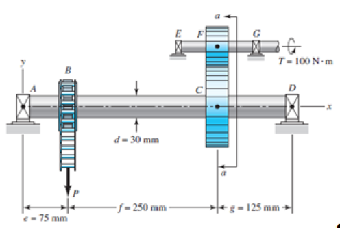
3-77* A torque T = 100 N · m is applied to the shaft EFG, which is running at constant speed and contains gear F. Gear F transmits torque to shaft ABCD through gear C, which drives the chain sprocket at B, transmitting a force P as shown. Sprocket B, gear C, and gear F have pitch diameters of a = 150, b = 250, and c = 125 mm, respectively. The contact force between the gears is transmitted through the pressure angle ϕ = 20°. Assuming no frictional losses and considering the bearings at A, D, E, and G to be simple supports, locate the point on shaft ABCD that contains the maximum tensile bending and maximum torsional shear stresses. Combine these stresses and determine the maximum principal normal and shear stresses in the shaft.
Want to see the full answer?
Check out a sample textbook solution
Chapter 11 Solutions
Shigley's Mechanical Engineering Design (McGraw-Hill Series in Mechanical Engineering)


- A 6-in-wide polyamide F-1 flat belt is used to connect a 4-in-diameter pulley to drive a larger pulley with an angular velocity ratio of 3. The center-to-center distance is 8 ft. The angular speed of the small pulley is 1850 rev/min as it delivers 2 hp. The service is such that a service factor Ks of 1.25 is appropriate. (a) Find Fc, Fi, F1a, and F2. (b) Find Ha, nfs, and belt length. (c) Find the dip.arrow_forward19 The figure shows a countershaft carrvino two V-helt pulleys and mounted in bearings at O and C. Fulley A receives power from a motor through a belt wwith the belt tension shown. The power is transmitted through the shaft and delivered to the belt on pullev B. Assume the belt tension on the c) For static analysis using a design factor ng = 2.8, use distortion energy theory to determine the loose side at B is 15 percent of the tension on the right side. The shaft is to be made of AISI 1035 CD steel. a) Determine the tensions in the belt on pulley B, b) Find the reaction forces, minimum safe diameter of the shaft at point A. 250 mo 450 mm 300 mm 2 kN 0.3 kN 200-mm dia. find dia. 250-mm dia.arrow_forwardQ-3 A 25-mm-diameter solid round bar has a groove 2.5-mm deep with a 2.5-mm radius machined into it. The bar is made of AISI 1050 CD steel and is subjected to a purely reversing torque of 250 N-m. For the S-N curve of this material, let f = 0.9. (a) Estimate the number of cycles to failure. (b) If the bar is also placed in an environment with a temperature of 400°C, estimate the number of cycles to failure.arrow_forward
- Use the general shaft layout given and determine critical diameters of the shaft based on infinite fatigue life with a design factor of 1.5. Check for yielding. Check the slopes at the bearings for satisfaction of the recommended limits in Table 7-2. Assume that the deflections for the pulleys are not likely to be critical. 10 in 500 lbf 75 lbf 8-in dia. Bearing at O 10.0" 500 lb d 75 lb Material 1040 Q and T 18 in Use the following shaft layout assuming a pulley transmits torque through a key and keyseat at location A to another pulley at location B. Assume the tensions in the belt at pulley Bare T₁ and T2, where T₁ is 15% of T2. NOTE: This is a multi-part question. Once an answer is submitted, you will be unable to return to this part. 10-in dia. 12 in T₂ 8.0⁰ T₁ 18.0" 10.0" I B pulley diameter = 8.0" Sut 113 kpsi T2 T1 pulley diameter = 10.0" Sy 86 kpsi 12.0" Bearing at C Using the DE-Goodman criteria and a design factor of 1.5, calculate the diameter based on the shaft's loadings…arrow_forwardFor the free body diagram of the shaft shown below, the rolling contact bearings are located at A and C. For the bearing at A, the desired design load for the bearing is Tangential Direction for Gear Y-X axes: Radial Direction for Gear Z-X axes: 1000 Ibf 500 Ibf A A В 500 Ibf 500 Ibf 250 Ibf 250 Ibfarrow_forwardA motor provides 60 hp power to a wheel B. It rotates a solid shaft in AISI 1020 steel, 4 cm in diameter, at a speed of 300 rpm. Power is drawn from the shaft using belts attached to pulleys A and C. (Use the table if necessary) (a) Draw the torque diagram of the driven shaft. (b) What is the safety factor of the driven shaft? Answer: 5.22 (c) Determine the angle of torsion of pulley C with respect to pulley A. Answer: -1.88°arrow_forward
- In the figure below, a motor with power 150kw and speed of 2500 rpm is connected to shaft 1(by coupling) in a clockwise direction. Shaft 2 is connected to shaft 1 by gears 1 and 2. If 30% of the power is consumed by the gear3 and 9% by the pulley and 61% by the sprocket, draw torque diagrams for both shafts. • Lengths: AB=90mm/BC=GH=50mm/CD3HI=60mm/DE=IJ=80mm 13 Gear3 E Gear2 14 15 16 Motor shafth 2. 17 Bearing Shaft1 Gear1 sprocketarrow_forwardThe disc clutch of an automobile is carried on a 2-inch 6-splined shaft and not to slide under load. The nominal dimensions are as follows: b = 0.25 D; t = 0.075 D and d = 0.85 D. The hub length of 150 % of shaft diameter. Determine the total horsepower transmitted at 3,600 rpm, if the yield strength of the shaft is 1,400 psiarrow_forwardDynamic load number C = 40500 N, revolution n = 840 rpm and Fr = 4500 of 6309 single row fixed radial bearing carrying N load; (a) Check and interpret whether it is selected correctly for Lh=20000 hours. (b) Calculate the dynamic load number of the bearing when the load remains the same and the life is doubled.arrow_forward
- The worm shaft shown in part a of the figure transmits 1.2 hp at 500 rev/min. A static force analysis gave the results shown in part b of the figure. Bearing A is to be an angular-contact ball bearing selected from Table 11–2, mounted to take the 555-lbf thrust load. The bearing at B is to take only the radial load, so an 02-series cylindrical roller bearing from Table 11–3 will be employed. Use an application factor of 1.2, a desired life of 30 kh, and a combined reliability goal of 0.99, assuming distribution data from manufacturer 2 in Table 11-6. Specify each Wom pitch cylinder Gear pitch cylinder (a) Worm and wom gear, h) force analysis of wom shaft krces in pounds. 595 72 35 145 bearing.arrow_forwardA bearing is subjected to a radial force of 8kN and a thrust force of 3 kN. Thevalues of X and Y factors are 0.56 and 1.5 respectively. The shaft rotates at 1200 RPM. The diameter of the shaft is 75mm and Bearing no. 6315 (C= 112000N) is selected for this application. Estimate the life of this bearing with 90% reliability.arrow_forwardThe gear forces shown act in planes parallel to the yz plane. The force on 20 in gear A is 300 lbf. Consider the bearings at O and B to be simple supports. For a static analysis and a factor of safety of 3.5, use both the DET and 16 in the MSST to determine the minimum safe diameter of the shaft. 10 in Consider the material to have a yield strength of 60 ksi. Gear A Solution: 24-in D. Gear C 10-in D. 20°arrow_forward
 Elements Of ElectromagneticsMechanical EngineeringISBN:9780190698614Author:Sadiku, Matthew N. O.Publisher:Oxford University Press
 Mechanics of Materials (10th Edition)Mechanical EngineeringISBN:9780134319650Author:Russell C. HibbelerPublisher:PEARSON
 Thermodynamics: An Engineering ApproachMechanical EngineeringISBN:9781259822674Author:Yunus A. Cengel Dr., Michael A. BolesPublisher:McGraw-Hill Education
 Control Systems EngineeringMechanical EngineeringISBN:9781118170519Author:Norman S. NisePublisher:WILEY
 Mechanics of Materials (MindTap Course List)Mechanical EngineeringISBN:9781337093347Author:Barry J. Goodno, James M. GerePublisher:Cengage Learning
 Engineering Mechanics: StaticsMechanical EngineeringISBN:9781118807330Author:James L. Meriam, L. G. Kraige, J. N. BoltonPublisher:WILEY