
Shigley's Mechanical Engineering Design (McGraw-Hill Series in Mechanical Engineering)
10th Edition
ISBN: 9780073398204
Author: Richard G Budynas, Keith J Nisbett
Publisher: McGraw-Hill Education
expand_more
expand_more
format_list_bulleted
Concept explainers
Videos
Textbook Question
Chapter 11, Problem 31P
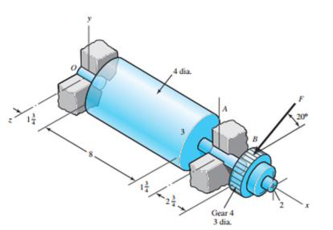
Shown in the figure is a gear-driven squeeze roll that mates with an idler roll. The roll is designed to exert a normal force of 35 lbf/in of roll length and a pull of 28 lbf/in on the material being processed. The roll speed is 350 rev/min, and a design life of 35 kh is desired. Use an application factor of 1.2, and select a pair of angular-contact 02-series ball bearings from Table 11-2 to be mounted at 0 and A. Use the same size bearings at both locations and a combined reliability of at least 0.92, assuming distribution data from manufacturer 2 in Table 11-6.
Expert Solution & Answer
Want to see the full answer?
Check out a sample textbook solution
Students have asked these similar questions
A cylinder with a nominal 2.5 in ID, a 4.0 in OD, and a 3.0 in length is to be mated with a solid shaft with a nominal 2.5 in diameter. A medium drive fit is desired (as defined in Table 7-9). The cylinder and shaft are made from steel, with Sy = 100 kpsi and E = 30 Mpsi. The coefficient of friction for the steel interface is 0.7.
a. Specify the maximum and minimum allowable diameters for both the cylinder hole and the shaft.
b. Determine the torque that can be transmitted through this joint, assuming the shaft and cylinder are both manufactured within their tolerances such that the minimum interference is achieved.
c. Suppose the shaft and cylinder are both manufactured within their tolerances such that the maximum interference is achieved. Check for yielding of the cylinder at its inner radius by finding the following:
i. The pressure at the interface
ii. The tangential and radial stresses in the cylinder, at its inner radius.
iii. The factor of safety for static yielding of the…
The press shown for Prob. 8-5 has a rated load of 5000 lbf. The twin screws have Acme threads,
a diameter of 2 in, and a pitch of in. Coefficients of friction are 0.05 for the threads and
0.08 for the collar bearings. Collar diameters are 3.5 in. The gears have an efficiency of 95 per-
cent and a speed ratio of 60:1. A slip clutch, on the motor shaft, prevents overloading. The full-
load motor speed is 1720 rev/min.
(a) When the motor is turned on, how fast will the press head move?
(b) What should be the horsepower rating of the motor?
Spur gears
Bearings
Motor
Worm
Bronze
bushings
-2L 's
Collar
bearing
3
The press
shown below has a rated load of 25 kN The twin screws have Acme
threads, a diameter of 56 mm, and a pitch of 5.5 mm. Coefficients of friction are
0.05 for the threads and 0.08 for the collar bearings. Collar diameters are
88 mm. The gears have an efficiency of 95 percent and a speed ratio of 60: 1.
The full-load motor speed is 1750 rev/min.
a. When the motor is turned on, how fast will the press head move?
b. What should be the horsepower rating of the motor?
Bearings
Motor
Spur gears
Bronze
bushings
(مزدوج)
Foot
Worm
Collar
bearing
Chapter 11 Solutions
Shigley's Mechanical Engineering Design (McGraw-Hill Series in Mechanical Engineering)
Ch. 11 - Manufacturer Rating Life, Revolutions Weibull...Ch. 11 - Manufacturer Rating Life, Revolutions Weibull...Ch. 11 - Manufacturer Rating Life, Revolutions Weibull...Ch. 11 - Problems 112 and 113 raise the question of the...Ch. 11 - Prob. 5PCh. 11 - Manufacturer Rating Life, Revolutions Weibull...Ch. 11 - Two ball bearings from different manufacturers are...Ch. 11 - 11-8 to 11-13 For the bearing application...Ch. 11 - 11-8 to 11-13 For the bearing application...Ch. 11 - 11-8 to 11-13 For the bearing application...
Ch. 11 - 11-8 to 11-13 For the bearing application...Ch. 11 - 11-8 to 11-13 For the bearing application...Ch. 11 - 11-8 to 11-13 For the bearing application...Ch. 11 - A countershaft carrying two V-belt pulleys is...Ch. 11 - A countershaft carrying two V-belt pulleys is...Ch. 11 - A countershaft carrying two V-belt pulleys is...Ch. 11 - A countershaft carrying two V-belt pulleys is...Ch. 11 - For the shaft application defined in Prob. 3-77,...Ch. 11 - For the shaft application defined in Prob. 3-79,...Ch. 11 - An 02-series single-row deep-groove ball bearing...Ch. 11 - An 02-series single-row deep-groove ball bearing...Ch. 11 - 11-22 to 11-26 An 02-series single-row deep-groove...Ch. 11 - 1122 to 1126 An 02-series single-row deep-groove...Ch. 11 - 1122 to 1126 An 02-series single-row deep-groove...Ch. 11 - 1122 to 1126 An 02-series single-row deep-groove...Ch. 11 - 1122 to 1126 An 02-series single-row deep-groove...Ch. 11 - The shaft shown in the figure is proposed as a...Ch. 11 - Repeat the requirements of Prob. 11-27 for the...Ch. 11 - The shaft shown in the figure is proposed as a...Ch. 11 - Repeat the requirements of Prob. 11-29 for the...Ch. 11 - Shown in the figure is a gear-driven squeeze roll...Ch. 11 - The figure shown is a geared countershaft with an...Ch. 11 - The figure is a schematic drawing of a...Ch. 11 - A gear-reduction unit uses the countershaft...Ch. 11 - The worm shaft shown in part a of the figure...Ch. 11 - In bearings tested at 2000 rev/min with a steady...Ch. 11 - A 16-tooth pinion drives the double-reduction...Ch. 11 - Estimate the remaining life in revolutions of an...Ch. 11 - The same 02-30 angular-contact ball bearing as in...Ch. 11 - A countershaft is supported by two tapered roller...Ch. 11 - For the shaft application defined in Prob. 3-74,...Ch. 11 - For the shaft application defined in Prob. 3-76,...Ch. 11 - Prob. 43PCh. 11 - The gear-reduction unit shown has a gear that is...
Knowledge Booster


Learn more about
Need a deep-dive on the concept behind this application? Look no further. Learn more about this topic, mechanical-engineering and related others by exploring similar questions and additional content below.Similar questions
- Figure below shows a portion of a pump that is gear-driven at uniform load and speed. The 25 mm diameter solod shaft supported by the bearings is to be made of machined AISI 1045 CD steel. The helical gear is subjected to the axial force F-498 y a radial load F- 750 N and a tangential load of F-1.995 N. Assume the component is g at room temperature of 70F and the material has s0s reliability factor. Hint: Be careful when you calculate the bending moment at the fillet, as all the three forces on the helical gear cause bending moment at the fillet. Calculate resultant bedina moment from all the three forces. Bending moment is completely reversed loading.) 25-mm solid round shaft Fillet Bending K, = 2.0 Torsional k, = 1.5 Axial K,18 F. F, F Pump Helical spur gear -50 mm -250-mm dia FIGURE 1. Identify the critical locations) of stress and show it clearly in a diagram. 2 Identity cleary, all the components of stresses (at the critical point) that will be calcurated (by drawing and clearty…arrow_forwardb) Design a self-aligning ball bearing with basic dynamic load rating of 69.5 KN to be used in the automobile industry to carry a thrust load of 1184 N. The expected life of the bearing is 5201 hours at 628 rpm. Take k=3 for all types of ball bearings. Take the value of the shock load factor as 1.7 and radial and axial load factors are 1.4 and 2.2 respectively, the rotational factor is 1. Calculate: i) Expected life of bearings in millions of revolutions ii) Design equivalent dynamic load in N iii) Basic equivalent dynamic load in N iv) Radial load acting on the bearing in Narrow_forwardProblem 4. A 16-tooth 240 Bhn steel spur pinion having a pressure angle of 20° and rotating at 720 rev/min drives a 28-tooth 240 Bhn steel gear having a 2.5 -in face and a diametral pitch of 5 teeth/in. Find the factor of safety of this drive based on bending strength if 17.5 hp is transmitted. Use Ko=Ks=1, Km=1.6 and Qv=7.arrow_forward
- For the geared countershaft with an overhanging pinion at C, the force on gear A is FA = 600 Ibf, and the shaft is to run at a speed of 420 rev/min. Consider an application factor of 1.2, a desired life of 40 kh, and combined reliability goal of 0.95 Select and specify the bearing required a) An angular contact ball bearing for mounting at O and b) A straight roller bearing for mounting at B Gear 3 24 dia. Gear 4 10 dia. 20arrow_forwardFigure below shows a portion of a pump that is gear-driven at uniform load and speed. The 25 mm diameter solod shaft supported by the bearings is to be made of machined AISI 1045 CD steel. The helical gear is subjected to the axial force F =499 y a radial load F = 741 N and a tangential load of F=2,006 N. Assume the component is operating at room temperature of 70°F and the material has 50% reliability factor. 25-mm solid Bending K, = 2.0 round shaft Fillet Torsional K = 1.5 F. F, Axial K, = 1.8 F Pump Helical spur gear 50 mm -250-mm dia.- FIGURE 1. Identify the critical location(s) of stress and show it clearly in a diagram. 2. Identify cleary, all the components of stresses (at the critical point) that will be calculated (by drawing and clearly showing the XYZ axes) and show it in a matrix form. Show which components of stresses will have a value zero or non-zero. 3. Calculate the principal stresses and principal directions. Show the principal stresses clearly in a stress element…arrow_forwardh Thoist, hoist 1₁ m mg G=5 Gear box Pshaft Ishaft, Pshaft Electrical machine 400 V 50 Hz Tower crane, which is driven by an electrical motor hoists a certain mass load on the height of 60 m. Electric motor produces 15000 W shaft power to lift this load and it is connected to the load via an ideal reduction (decreases speed) gear box with G = 5 gear coefficient, the radius of the hoist gear is ₁ = 0.2 m. Find, how long does it take to lift the load and the mass of the load. Electrical machine is supplied with 50 Hz, and it has 3 pole pair. Assume that motor accelerates instantaneously and there is no rotor inertia. Time, spent on lifting: Mass of the load:arrow_forward
- For the given details, design a self-aligning ball bearing to be used in a textile machinery to carry a combined radial load of 6139 N and thrust load of 1153 N. The expected life of the bearing is 150 millions of revolutions at 734 rpm. Take k=p=3 for all types of ball bearings. Assume uniform steady state load and take the corresponding factor as 1.1. Radial and axial load factors are 0.65 and 1.2 respectively, rotational speed factor is 1. Note: Please upload your handwritten working/solution to the link provided. Dynamic load on the bearing in N Dynamic equivalent load considering steady state load factor in N Dynamic load carrying capacity in N -arrow_forwardThe design load on a ball bearing is 413 lbf and an application factor of 1.2 is appro- priate. The speed of the shaft is to be 300 rev/min, the life to be 30 kh with a reliability of 0.99. What is the C10 catalog entry to be sought (or exceeded) when searching for a deep-groove bearing in a manufacturer's catalog on the basis of 106 revolutions for rat- ing life? The Weibull parameters are xo = 0.02, (0 – xo) = 4.439, and b = 1.483. %3Darrow_forward5- Give the suitable dimensions of a leather open flat-belt system according to the standards having the following details: the source power is 28 Hp. @500 rpm. The driver shaft is 300 mm diameter. The velocity ratio is 1:2.8. The belt material may be cotton woven and the pulleys are rubber faced. The center distance is 3m, take the allowable stress intensity for leather belt is 4.8 MPa. Take safety factor of 1.5.arrow_forward
- A 50 mm transmission shaft transmitting 15 kW power at 200 rpm is supported on two deep grove ball bearings 750 mm apart and two gears are key to it. The pinion and gear have 30 and 100 teeth respectively. The pinion is located at 100 mm to the left of the right bearing, whereas the gear is located at 150 mm to the right of the left bearing The module and pressure angle of gear is 5 and 20o involute. Pinion delivers power horizontally to the right and gear received power in a vertical direction from below as shown in Figure l. The expected life of 15,00 h assumes the torque is the same for both pinion and gear and the bearings are under radial load only. Find the pitch diameters of pinion and gear. The torque transmits by the shaft Find force FC and FD Select suitable deep groove ball bearings at A and B B 150 500 100 Fe N-arrow_forwardMechanical design A shaft with the following data: 1- The pulley (A) is 1000 mm in diameter and weight 300N. 2- The gear (B) pitch diameter is 600mm and weight -250N. 3- The pulley is keyed to the shaft at 400mm to the left of left hand bearing. 4-the distance between bearing C and B is 1250 mm. 5- The power is 20 kW at 750 rpm. 6- Tension ratio T1 / T2-2.5 7- The shaft d.livers power to a gear placed horizontally in front, the pressure angel of gear is 20. 8- The allowable shear stress is 70N / mm, kt-2 and km- 1.5. Determine: the diameter of shaftarrow_forwardA 20° 20-tooth cast-iron spur pinion having a module of 4 mm drives a 32-tooth cast-iron gear. Find the contact stress if the pinion speed is 1020 rev/min, the face width is 50 mm, and 10 kW of power is transmitted. Refer to table number 14-8 for elastic coefficient. The contact stress is MPa.arrow_forward
arrow_back_ios
SEE MORE QUESTIONS
arrow_forward_ios
Recommended textbooks for you
 Elements Of ElectromagneticsMechanical EngineeringISBN:9780190698614Author:Sadiku, Matthew N. O.Publisher:Oxford University Press
 Mechanics of Materials (10th Edition)Mechanical EngineeringISBN:9780134319650Author:Russell C. HibbelerPublisher:PEARSON
 Thermodynamics: An Engineering ApproachMechanical EngineeringISBN:9781259822674Author:Yunus A. Cengel Dr., Michael A. BolesPublisher:McGraw-Hill Education
 Control Systems EngineeringMechanical EngineeringISBN:9781118170519Author:Norman S. NisePublisher:WILEY
 Mechanics of Materials (MindTap Course List)Mechanical EngineeringISBN:9781337093347Author:Barry J. Goodno, James M. GerePublisher:Cengage Learning
 Engineering Mechanics: StaticsMechanical EngineeringISBN:9781118807330Author:James L. Meriam, L. G. Kraige, J. N. BoltonPublisher:WILEY
Elements Of Electromagnetics
Mechanical Engineering
ISBN:9780190698614
Author:Sadiku, Matthew N. O.
Publisher:Oxford University Press
Mechanics of Materials (10th Edition)
Mechanical Engineering
ISBN:9780134319650
Author:Russell C. Hibbeler
Publisher:PEARSON
Thermodynamics: An Engineering Approach
Mechanical Engineering
ISBN:9781259822674
Author:Yunus A. Cengel Dr., Michael A. Boles
Publisher:McGraw-Hill Education
Control Systems Engineering
Mechanical Engineering
ISBN:9781118170519
Author:Norman S. Nise
Publisher:WILEY
Mechanics of Materials (MindTap Course List)
Mechanical Engineering
ISBN:9781337093347
Author:Barry J. Goodno, James M. Gere
Publisher:Cengage Learning
Engineering Mechanics: Statics
Mechanical Engineering
ISBN:9781118807330
Author:James L. Meriam, L. G. Kraige, J. N. Bolton
Publisher:WILEY
How to Measure Threads; Author: PracticalMachinist;https://www.youtube.com/watch?v=Uuy7EViS7Kc;License: Standard Youtube License