
Loose Leaf for Engineering Circuit Analysis Format: Loose-leaf
9th Edition
ISBN: 9781259989452
Author: Hayt
Publisher: Mcgraw Hill Publishers
expand_more
expand_more
format_list_bulleted
Videos
Textbook Question
Chapter 15, Problem 17E
For the circuit of Fig. 15.56, construct a magnitude and phase Bode plot for the transfer function H(s) = Vout/Vin and circuit values of R1 = 500 Ω, R2 = 40 kΩ, and C1 = 10 nF.
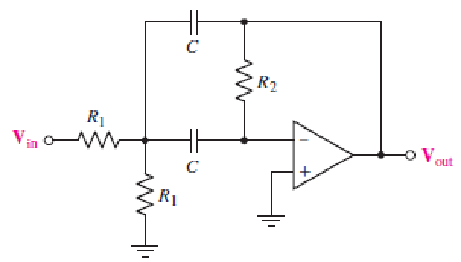
■ FIGURE 15.56
Expert Solution & Answer
Want to see the full answer?
Check out a sample textbook solution
Students have asked these similar questions
A coil of resistance 25 and inductance
100 mH is connected in series with a
capacitance of 0.12 µF across a 200 V,
variable frequency supply. Calculate:
a) The resonant frequency
b)
The current at resonance, and
c)
The factor by which the voltage across
each reactance is greater than the
supply voltage.
ANS: (a) 1452.879 Hz (1.453 kHz) (b) 8 <0° A
(c) 36.515
A supply voltage of 3 V is applied to a series
R–L–C circuit whose resistance is 12 ohms ,
inductance is 7.5 mH and capacitance is
0.5µF. Determine (a) the current flowing at
resonance, (b) the current flowing at a frequency 2.5% below the resonant frequency
and (c) the impedance of the circuit when the frequency is 1% lower than the resonant
frequency.
1. A parallel R-L-C circuit is fed by a constant
current source of variable frequency. The circuit
resonates at 100 kHz and the Q-factor
measured at this frequency is 5. Find the
frequencies at which the amplitude of the
voltage across the circuit falls to (a) 70.7% (b)
50% of the resonant frequency amplitude. [(a)
90.5 kHz ; 110.5 kHz (b) 84.18 kHz ; 118.8 kHz]
Chapter 15 Solutions
Loose Leaf for Engineering Circuit Analysis Format: Loose-leaf
Ch. 15.1 - Write an expression for the transfer function of...Ch. 15.2 - Calculate HdB at = 146 rad/s if H(s) equals (a)...Ch. 15.2 - Prob. 3PCh. 15.2 - Draw the Bode phase plot for the transfer function...Ch. 15.2 - Construct a Bode magnitude plot for H(s) equal to...Ch. 15.2 - Draw the Bode phase plot for H(s) equal to (a)...Ch. 15.2 - Prob. 7PCh. 15.3 - A parallel resonant circuit is composed of the...Ch. 15.3 - Prob. 9PCh. 15.4 - A marginally high-Q parallel resonant circuit has...
Ch. 15.5 - A series resonant circuit has a bandwidth of 100...Ch. 15.6 - Referring to the circuit of Fig. 15.25a, let R1 =...Ch. 15.6 - Prob. 13PCh. 15.6 - Prob. 14PCh. 15.6 - The series combination of 10 and 10 nF is in...Ch. 15.7 - A parallel resonant circuit is defined by C = 0.01...Ch. 15.8 - Design a high-pass filter with a cutoff frequency...Ch. 15.8 - Design a bandpass filter with a low-frequency...Ch. 15.8 - Design a low-pass filter circuit with a gain of 30...Ch. 15 - For the RL circuit in Fig. 15.52, (a) determine...Ch. 15 - For the RL circuit in Fig. 15.52, switch the...Ch. 15 - Examine the series RLC circuit in Fig. 15.53, with...Ch. 15 - For the circuit in Fig. 15.54, (a) derive an...Ch. 15 - For the circuit in Fig. 15.55, (a) derive an...Ch. 15 - For the circuit in Fig. 15.56, (a) determine the...Ch. 15 - For the circuit in Fig. 15.57, (a) determine the...Ch. 15 - Sketch the Bode magnitude and phase plots for the...Ch. 15 - Use the Bode approach to sketch the magnitude of...Ch. 15 - If a particular network is described by transfer...Ch. 15 - Use MATLAB to plot the magnitude and phase Bode...Ch. 15 - Determine the Bode magnitude plot for the...Ch. 15 - Determine the Bode magnitude and phase plot for...Ch. 15 - Prob. 15ECh. 15 - Prob. 16ECh. 15 - For the circuit of Fig. 15.56, construct a...Ch. 15 - Construct a magnitude and phase Bode plot for the...Ch. 15 - For the circuit in Fig. 15.54, use LTspice to...Ch. 15 - For the circuit in Fig. 15.55, use LTspice to...Ch. 15 - Prob. 21ECh. 15 - A certain parallel RLC circuit is built using...Ch. 15 - A parallel RLC network is constructed using R = 5...Ch. 15 - Prob. 24ECh. 15 - Delete the 2 resistor in the network of Fig....Ch. 15 - Delete the 1 resistor in the network of Fig....Ch. 15 - Prob. 28ECh. 15 - Prob. 29ECh. 15 - Prob. 30ECh. 15 - A parallel RLC network is constructed with a 200 H...Ch. 15 - Prob. 32ECh. 15 - A parallel RLC circuit is constructed such that it...Ch. 15 - Prob. 34ECh. 15 - Prob. 35ECh. 15 - An RLC circuit is constructed using R = 5 , L = 20...Ch. 15 - Prob. 37ECh. 15 - Prob. 38ECh. 15 - For the network of Fig. 15.25a, R1 = 100 , R2 =...Ch. 15 - Assuming an operating frequency of 200 rad/s, find...Ch. 15 - Prob. 41ECh. 15 - Prob. 42ECh. 15 - For the circuit shown in Fig. 15.64, the voltage...Ch. 15 - Prob. 44ECh. 15 - Prob. 45ECh. 15 - Prob. 46ECh. 15 - The filter shown in Fig. 15.66a has the response...Ch. 15 - Prob. 48ECh. 15 - Examine the filter for the circuit in Fig. 15.68....Ch. 15 - Examine the filter for the circuit in Fig. 15.69....Ch. 15 - (a)Design a high-pass filter with a corner...Ch. 15 - (a) Design a low-pass filter with a break...Ch. 15 - Prob. 53ECh. 15 - Prob. 54ECh. 15 - Design a low-pass filter characterized by a...Ch. 15 - Prob. 56ECh. 15 - The circuit in Fig. 15.70 is known as a notch...Ch. 15 - (a) Design a two-stage op amp filter circuit with...Ch. 15 - Design a circuit which removes the entire audio...Ch. 15 - Prob. 61ECh. 15 - If a high-pass filter is required having gain of 6...Ch. 15 - (a) Design a second-order high-pass Butterworth...Ch. 15 - Design a fourth-order high-pass Butterworth filter...Ch. 15 - (a) Design a Sallen-Key low-pass filter with a...Ch. 15 - (a) Design a Sallen-Key low-pass filter with a...Ch. 15 - A piezoelectric sensor has an equivalent circuit...Ch. 15 - Design a parallel resonant circuit for an AM radio...Ch. 15 - The network of Fig. 15.72 was implemented as a...Ch. 15 - Determine the effect of component tolerance on the...
Additional Engineering Textbook Solutions
Find more solutions based on key concepts
Find I0 and I1 in the circuit in Fig.P2.12.
Basic Engineering Circuit Analysis
Explain the main function of each of the following major components of a PLC: a. Processor module (CPU) b. I/O ...
Programmable Logic Controllers
Assume a telephone signal travels through a cable at two-thirds the speed of light. How long does it take the s...
Electric Circuits (10th Edition)
Design an ideal inverting op-amp circuit such that the voltage gain is Av=25 . The maximum current in any resis...
Microelectronics: Circuit Analysis and Design
The current source in the circuit shown generates the current pulse
Find (a) v (0); (b) the instant of time gr...
Electric Circuits. (11th Edition)
When travelers from the USA and Canada visit Europe, they encounter a different power distribution system. Wall...
Electric machinery fundamentals
Knowledge Booster


Learn more about
Need a deep-dive on the concept behind this application? Look no further. Learn more about this topic, electrical-engineering and related others by exploring similar questions and additional content below.Similar questions
- Discussions: 1) For the following filter, 0.15pF Vout Vin 3300 2) Explain what a band-pass filter is, and how it differs from either a low-pass or a high-pass filter circuit. Also, explain what a band-stop filter is, and draw Bode plots representative of both band-pass and band-stop filter types.arrow_forward15. A parallel resonant circuit is resonant at 400 Hz with Qo If a current of 2 mA is applied to the circuit, use approximate methods to find the cyclic frequency of the current if (a) the voltage across the circuit has a magnitude of 0.5 V; (b) the resistor current has a magnitude of 0.5 mA. = 8 and R = 500 S2. 443.3 and 356.7 Hz 496.8 and 303.2 Hz|arrow_forwardQ5) 2) Use the RLC circuit below to answer the following questions. R1 L1 zt √FL C (18) NS = R 10Vrms *15= 10M 10 -= 1/5 = 1/2 = 0.66 Vs 1 = 0.66 K√2 = 0.933 For the above circuit, determine: 15Ω 2mH C1 H 50pF a) The resonant frequency in kHz. b) The voltage drop across the resistor at the resonant frequency. c) Determine the rms and peak values of the circuit current at the resonant frequencyarrow_forward
- Design an active low-pass filter with dc gain of 0.25 and a corner frequency of 500 Hz.arrow_forward1. A series RLC circuit has a Q of 75 and a pass band between half-power frequencies of 160 cps. Calculate the frequency of resonance and upper and lower frequencies of the pass band. 2. A 15.9 uF capacitor and a 15.1 mH inductor are connected in parallel. In series with these units are a variable resistor R and an adjustable device X, joined in series. (a) Determine the kind and size of device X (inductance in Henry or capacitance in Farad) when the circuit is connected to a 50 volt 400 cps source and is adjusted to resonance. (b) For the resonant condition, calculate the value of R if the voltage drop across the paralleled units is to be 100 volts. 3. An impedance coil having a resistance of 30 ohms and a 50 cps inductive reactance of 33.3 ohms is connected to a 125 volt 60 cps source. A series circuit consisting of a 20 ohm resistor and a variable capacitor is then connected in parallel with the coil. (a) for what values of capacitance will the circuit be in resonance? (b)…arrow_forwardA coil having an inductance of 50 mH and resistance of 8.0 is connected in series with a 25 µF capacitor across a 100 V a.c. supply. Determine: a) The resonant frequency of the circuit, and b) The current flowing at resonance. ANS: (a) 142.4 Hz (b) 12.5 A.arrow_forward
- A series circuit consists of a reactor of 0.1 henry inductance and 5 ohms resistance and a capacitor of 25.5 μ F capacitance. Find the resonance frequency and the percentage change in the current for a divergence of 1 percent from the resonance frequency. [100 Hz, 1.96% at 99 Hz; 4.2% at 101 Hz]arrow_forwardA series RLC network has R = 1.5 KQ, L = 50 mH, and C = 1 microF. Calculate the impedance (in ko) at resonance. (Use 1 decimal place. Unit is not required.)arrow_forwardCalculate Resonance Frequency, Cutoff Frequencies, Bandwidth, and Quality Factor for the RLC Circuit. R3 470 R4 L3 C3 V1 2700 470uH 10NFarrow_forward
- A 15.9-uF capacitor and a 15.1-mH inductor are connected in parallel. In series with these units are a variable resistor R and an adjustable reactive device X. joined inseries. (a) Determine the kind and size of device X inductance in henrys orcapacitance in μF) when the circuit is connected to a 50-volf 400-cycle source and is adjusted to resonance. (b) For the resonant condition calculate the value of R if the voltage drop across the paralleled units is to be 100 V.arrow_forwardDerive and plot the magnitude and phase responses of the first order difference system, y[n] = x[n]–x[n − 1]. ..arrow_forwardQ.3/ Find the difference equation that describe, the following digital filter: M (Z) E (2) 27²-3.52 +1.9 2²³²-2.77² +Z-0.95arrow_forward
arrow_back_ios
SEE MORE QUESTIONS
arrow_forward_ios
Recommended textbooks for you
 Introductory Circuit Analysis (13th Edition)Electrical EngineeringISBN:9780133923605Author:Robert L. BoylestadPublisher:PEARSON
 Delmar's Standard Textbook Of ElectricityElectrical EngineeringISBN:9781337900348Author:Stephen L. HermanPublisher:Cengage Learning
 Programmable Logic ControllersElectrical EngineeringISBN:9780073373843Author:Frank D. PetruzellaPublisher:McGraw-Hill Education
 Fundamentals of Electric CircuitsElectrical EngineeringISBN:9780078028229Author:Charles K Alexander, Matthew SadikuPublisher:McGraw-Hill Education
 Electric Circuits. (11th Edition)Electrical EngineeringISBN:9780134746968Author:James W. Nilsson, Susan RiedelPublisher:PEARSON
 Engineering ElectromagneticsElectrical EngineeringISBN:9780078028151Author:Hayt, William H. (william Hart), Jr, BUCK, John A.Publisher:Mcgraw-hill Education,
Introductory Circuit Analysis (13th Edition)
Electrical Engineering
ISBN:9780133923605
Author:Robert L. Boylestad
Publisher:PEARSON
Delmar's Standard Textbook Of Electricity
Electrical Engineering
ISBN:9781337900348
Author:Stephen L. Herman
Publisher:Cengage Learning
Programmable Logic Controllers
Electrical Engineering
ISBN:9780073373843
Author:Frank D. Petruzella
Publisher:McGraw-Hill Education
Fundamentals of Electric Circuits
Electrical Engineering
ISBN:9780078028229
Author:Charles K Alexander, Matthew Sadiku
Publisher:McGraw-Hill Education
Electric Circuits. (11th Edition)
Electrical Engineering
ISBN:9780134746968
Author:James W. Nilsson, Susan Riedel
Publisher:PEARSON
Engineering Electromagnetics
Electrical Engineering
ISBN:9780078028151
Author:Hayt, William H. (william Hart), Jr, BUCK, John A.
Publisher:Mcgraw-hill Education,
Resonance Circuits: LC Inductor-Capacitor Resonating Circuits; Author: Physics Videos by Eugene Khutoryansky;https://www.youtube.com/watch?v=Mq-PF1vo9QA;License: Standard YouTube License, CC-BY