
Loose Leaf for Engineering Circuit Analysis Format: Loose-leaf
9th Edition
ISBN: 9781259989452
Author: Hayt
Publisher: Mcgraw Hill Publishers
expand_more
expand_more
format_list_bulleted
Videos
Textbook Question
Chapter 15, Problem 2E
For the RL circuit in Fig. 15.52, switch the positions of the resistor and inductor such that vout is the voltage drop across the resistor. (a) Write an expression or the transfer function, defined as H(jω) = vout/vin; (b) for the case of R = 200 Ω and L = 5 mH, construct a plot of the magnitude and phase as a function of frequency; and (c) evaluate the magnitude and phase at a frequency of 10 kHz.
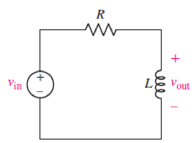
■ FIGURE 15.52
Expert Solution & Answer
Want to see the full answer?
Check out a sample textbook solution
Students have asked these similar questions
A series circuit with R = 10 2, L = 0.1 H and C =
%3D
%3D
%3D
50 µF has an applied voltage V = 50 L0° with a
variable frequency. Find the resonant frequency,
the value of frequency at which maximum voltage
occurs across the inductor and the value of fre-
quency at which maximum voltage occurs across the
сараcitor.
(a) find the transfer function
(b) Determine the corner frequency
(c) Find an expression for |H(w) and sketch the relationship
between |H(w)| vs.w
(d) Determine the voltage and power values at the output when
the magnitude of the input voltage is 10 V and the frequency
takes the following values 0.01wc, 0.1wc, 2wc, 2wc
Q Search
48
*
v,(t)
200 £2
ww
0.1 H (1)
11
Help plz:
Design a Wein bridge oscillator to generate a sinusoidal waveform of frequency 5KHz.
Chapter 15 Solutions
Loose Leaf for Engineering Circuit Analysis Format: Loose-leaf
Ch. 15.1 - Write an expression for the transfer function of...Ch. 15.2 - Calculate HdB at = 146 rad/s if H(s) equals (a)...Ch. 15.2 - Prob. 3PCh. 15.2 - Draw the Bode phase plot for the transfer function...Ch. 15.2 - Construct a Bode magnitude plot for H(s) equal to...Ch. 15.2 - Draw the Bode phase plot for H(s) equal to (a)...Ch. 15.2 - Prob. 7PCh. 15.3 - A parallel resonant circuit is composed of the...Ch. 15.3 - Prob. 9PCh. 15.4 - A marginally high-Q parallel resonant circuit has...
Ch. 15.5 - A series resonant circuit has a bandwidth of 100...Ch. 15.6 - Referring to the circuit of Fig. 15.25a, let R1 =...Ch. 15.6 - Prob. 13PCh. 15.6 - Prob. 14PCh. 15.6 - The series combination of 10 and 10 nF is in...Ch. 15.7 - A parallel resonant circuit is defined by C = 0.01...Ch. 15.8 - Design a high-pass filter with a cutoff frequency...Ch. 15.8 - Design a bandpass filter with a low-frequency...Ch. 15.8 - Design a low-pass filter circuit with a gain of 30...Ch. 15 - For the RL circuit in Fig. 15.52, (a) determine...Ch. 15 - For the RL circuit in Fig. 15.52, switch the...Ch. 15 - Examine the series RLC circuit in Fig. 15.53, with...Ch. 15 - For the circuit in Fig. 15.54, (a) derive an...Ch. 15 - For the circuit in Fig. 15.55, (a) derive an...Ch. 15 - For the circuit in Fig. 15.56, (a) determine the...Ch. 15 - For the circuit in Fig. 15.57, (a) determine the...Ch. 15 - Sketch the Bode magnitude and phase plots for the...Ch. 15 - Use the Bode approach to sketch the magnitude of...Ch. 15 - If a particular network is described by transfer...Ch. 15 - Use MATLAB to plot the magnitude and phase Bode...Ch. 15 - Determine the Bode magnitude plot for the...Ch. 15 - Determine the Bode magnitude and phase plot for...Ch. 15 - Prob. 15ECh. 15 - Prob. 16ECh. 15 - For the circuit of Fig. 15.56, construct a...Ch. 15 - Construct a magnitude and phase Bode plot for the...Ch. 15 - For the circuit in Fig. 15.54, use LTspice to...Ch. 15 - For the circuit in Fig. 15.55, use LTspice to...Ch. 15 - Prob. 21ECh. 15 - A certain parallel RLC circuit is built using...Ch. 15 - A parallel RLC network is constructed using R = 5...Ch. 15 - Prob. 24ECh. 15 - Delete the 2 resistor in the network of Fig....Ch. 15 - Delete the 1 resistor in the network of Fig....Ch. 15 - Prob. 28ECh. 15 - Prob. 29ECh. 15 - Prob. 30ECh. 15 - A parallel RLC network is constructed with a 200 H...Ch. 15 - Prob. 32ECh. 15 - A parallel RLC circuit is constructed such that it...Ch. 15 - Prob. 34ECh. 15 - Prob. 35ECh. 15 - An RLC circuit is constructed using R = 5 , L = 20...Ch. 15 - Prob. 37ECh. 15 - Prob. 38ECh. 15 - For the network of Fig. 15.25a, R1 = 100 , R2 =...Ch. 15 - Assuming an operating frequency of 200 rad/s, find...Ch. 15 - Prob. 41ECh. 15 - Prob. 42ECh. 15 - For the circuit shown in Fig. 15.64, the voltage...Ch. 15 - Prob. 44ECh. 15 - Prob. 45ECh. 15 - Prob. 46ECh. 15 - The filter shown in Fig. 15.66a has the response...Ch. 15 - Prob. 48ECh. 15 - Examine the filter for the circuit in Fig. 15.68....Ch. 15 - Examine the filter for the circuit in Fig. 15.69....Ch. 15 - (a)Design a high-pass filter with a corner...Ch. 15 - (a) Design a low-pass filter with a break...Ch. 15 - Prob. 53ECh. 15 - Prob. 54ECh. 15 - Design a low-pass filter characterized by a...Ch. 15 - Prob. 56ECh. 15 - The circuit in Fig. 15.70 is known as a notch...Ch. 15 - (a) Design a two-stage op amp filter circuit with...Ch. 15 - Design a circuit which removes the entire audio...Ch. 15 - Prob. 61ECh. 15 - If a high-pass filter is required having gain of 6...Ch. 15 - (a) Design a second-order high-pass Butterworth...Ch. 15 - Design a fourth-order high-pass Butterworth filter...Ch. 15 - (a) Design a Sallen-Key low-pass filter with a...Ch. 15 - (a) Design a Sallen-Key low-pass filter with a...Ch. 15 - A piezoelectric sensor has an equivalent circuit...Ch. 15 - Design a parallel resonant circuit for an AM radio...Ch. 15 - The network of Fig. 15.72 was implemented as a...Ch. 15 - Determine the effect of component tolerance on the...
Additional Engineering Textbook Solutions
Find more solutions based on key concepts
How many coulombs do 93.8 1016 electrons represent?
Principles Of Electric Circuits
Design an ideal inverting op-amp circuit such that the voltage gain is Av=25 . The maximum current in any resis...
Microelectronics: Circuit Analysis and Design
When travelers from the USA and Canada visit Europe, they encounter a different power distribution system. Wall...
Electric machinery fundamentals
Identify the type of input and output configuration for each diff-amp in Figure 18-35.
Electronics Fundamentals: Circuits, Devices & Applications
The current source in the circuit shown generates the current pulse
Find (a) v (0); (b) the instant of time gr...
Electric Circuits. (11th Edition)
Write the nodal equations for the network of Fig. 8.137 using the general approach. Find the nodal voltages usi...
Introductory Circuit Analysis (13th Edition)
Knowledge Booster


Learn more about
Need a deep-dive on the concept behind this application? Look no further. Learn more about this topic, electrical-engineering and related others by exploring similar questions and additional content below.Similar questions
- Derive and plot the magnitude and phase responses of the first order difference system, y[n] = x[n]–x[n − 1]. ..arrow_forwardGiven the series RLC circuit in the following figure: (a) Derive the expression for the half-power frequencies, the resonant frequency, the bandwidth, and the quality factor. (b) Compute the quantities in part (a) if R = 10, L = 50mH, and C = 10μF i(t) R L Vin(t) Carrow_forwardProblem Solving Coverage: BJT Small Signal Analysis Instruction: WRITE the complete solutions and box your final answer. Use three (3) decimal places in your final answer. For the figure below: H 6.8 µF Determine the following: B. AC Analysis: www ww 68 kf 16 k2 16 V 2.2kQ 4. Solve the value of Zi, Zo, Av and Ai 2. Solve for re 3. Derive the equation of Zi, Zo, Av and Ai 0.75 k 6.8 µF H 3-100 10 µF 5.6 karrow_forward
- A 15.9-uF capacitor and a 15.1-mH inductor are connected in parallel. In series with these units are a variable resistor R and an adjustable reactive device X. joined inseries. (a) Determine the kind and size of device X inductance in henrys orcapacitance in μF) when the circuit is connected to a 50-volf 400-cycle source and is adjusted to resonance. (b) For the resonant condition calculate the value of R if the voltage drop across the paralleled units is to be 100 V.arrow_forward2. Find the values of resistance R and inductance L in the circuit of Fig. 15.19. [R=131 S2, L=0.545 H] 40HF - 1.52-35° A 240 V. 50 Hzarrow_forwardV:OV 3G !!.: Classroom > docs.google.com • * الاسم الرباعي الكامل Your answer Engineering and Numerical Analysis Lecture: Safa Al-waily 01| plot the Amplidude s phase spectyum (signal & double side) Q2 |Fimd x plot h complex form of (Fis) for he fenetion. Scanned by TapScanner 1 Add file Submit Clear form Never submit passwords through Google Forms. + •.. 5arrow_forward
- If the system with a transfer function shown in the block diagram if an input signal is applied x(t)= 2*Sin(wt), obtain the amplitude of the output signal for the frequencies indicated in the table Frequency [rad/s] Output amplitude Y(wt) 0.5 2s+8 Sine Wave Scope Transfer Fon 10 infinitearrow_forward1. The mathematical expression of the frequency spectrum of a general FM signal shows that it has technically a limited bandwidth a wide bandwidth an infinite bandwidth narrow bandwidth none of the choices 2. The break frequency for commercial FM broadcast of the preemphasis and deemphasis network is 2.122 kHz 2122 kHz 75 kHz 75 Hz none of the choicesarrow_forwardI DOK In the circuit shown in the given figure, determine the frequency response function in the form: V(w) H. (jw)= 1,400) 0 + Vjos) ww R₁ C H 145/(0) 1,0) A R₂ Vjos)arrow_forward
- Determine whether the following discrete-time signals are periodic, and, if so, state the fundamental period, No. a. a[n] = 0.5 cos("/6n+"/3) b. b[n] = E=-0 8[n – 6k] c. c[n] = 0.5 sin(3n) A continuous valued 9 kHz sinusoid is sampled at a rate of 48k samples/sec to produce a sequence x[n]. Determine if the sequence is periodic and if so, what is No, the period. Let x[n] 0.8"u[n] and y[n] = (-0.8)"u[n] Plot x[n] and y[n] for n = -2, -1, ... , 4, 5 b. Find En=-ox[n] Find En=-o y[n] а. c. Find the energy in x[n] Find the energy in y[n] d. е. A discrete time system is described by the difference equation y[n] : x[n] is the input and y[n] is the output. Plot y[n] for: х[п] — x[п — 1], where а. x[n] = 8[n] b. x[n] = u[n] - [n – 3]arrow_forward1:53:24 C RLC circuit with a sinusoidal input voltage, the amplitude of the current passing through the circuit (lo in mA) is plotted as a function of frequency for two cases Curve 1 with Ry, L1, and .Curve 2 with R, L2 as shown in the next figure The value of the capacitor used in the circuits is C=0.01 micro Farads :The quality factor (Q1) for curve 1 is about 7.5 5- 2.5 I to 1 10 I 10 I to Frequency (f), Harrow_forwardFor the OP-Amp circuit below: a) Derive the transfer function, T(s). b) Calculate the magnitude of the filter. c) What is the order of this filter? d) What type of filter is this? e) Draw the S-Plane Singularities shown the radial distance from the origin. 8Ω V10 O v2 1/16 F 40arrow_forward
arrow_back_ios
SEE MORE QUESTIONS
arrow_forward_ios
Recommended textbooks for you
 Introductory Circuit Analysis (13th Edition)Electrical EngineeringISBN:9780133923605Author:Robert L. BoylestadPublisher:PEARSON
 Delmar's Standard Textbook Of ElectricityElectrical EngineeringISBN:9781337900348Author:Stephen L. HermanPublisher:Cengage Learning
 Programmable Logic ControllersElectrical EngineeringISBN:9780073373843Author:Frank D. PetruzellaPublisher:McGraw-Hill Education
 Fundamentals of Electric CircuitsElectrical EngineeringISBN:9780078028229Author:Charles K Alexander, Matthew SadikuPublisher:McGraw-Hill Education
 Electric Circuits. (11th Edition)Electrical EngineeringISBN:9780134746968Author:James W. Nilsson, Susan RiedelPublisher:PEARSON
 Engineering ElectromagneticsElectrical EngineeringISBN:9780078028151Author:Hayt, William H. (william Hart), Jr, BUCK, John A.Publisher:Mcgraw-hill Education,
Introductory Circuit Analysis (13th Edition)
Electrical Engineering
ISBN:9780133923605
Author:Robert L. Boylestad
Publisher:PEARSON
Delmar's Standard Textbook Of Electricity
Electrical Engineering
ISBN:9781337900348
Author:Stephen L. Herman
Publisher:Cengage Learning
Programmable Logic Controllers
Electrical Engineering
ISBN:9780073373843
Author:Frank D. Petruzella
Publisher:McGraw-Hill Education
Fundamentals of Electric Circuits
Electrical Engineering
ISBN:9780078028229
Author:Charles K Alexander, Matthew Sadiku
Publisher:McGraw-Hill Education
Electric Circuits. (11th Edition)
Electrical Engineering
ISBN:9780134746968
Author:James W. Nilsson, Susan Riedel
Publisher:PEARSON
Engineering Electromagnetics
Electrical Engineering
ISBN:9780078028151
Author:Hayt, William H. (william Hart), Jr, BUCK, John A.
Publisher:Mcgraw-hill Education,
Resonance Circuits: LC Inductor-Capacitor Resonating Circuits; Author: Physics Videos by Eugene Khutoryansky;https://www.youtube.com/watch?v=Mq-PF1vo9QA;License: Standard YouTube License, CC-BY