
Loose Leaf for Engineering Circuit Analysis Format: Loose-leaf
9th Edition
ISBN: 9781259989452
Author: Hayt
Publisher: Mcgraw Hill Publishers
expand_more
expand_more
format_list_bulleted
Videos
Textbook Question
Chapter 15, Problem 4E
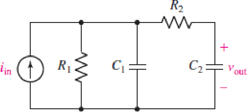
For the circuit in Fig. 15.54, (a) derive an algebraic expression for the transfer function H(jω) = vout/iin terms of circuit components R1, R2, C1, and C2; and (b) evaluate the magnitude of H at frequencies of 100 Hz, 10 kHz, and 1 MHz for case where R1 = 20 kΩ, R2 = 5 kΩ, C1 = 10 nF, and C2 = 40 nF.
FIGURE 15.54
Expert Solution & Answer
Want to see the full answer?
Check out a sample textbook solution
Students have asked these similar questions
VS+
-SA
V1
5
V2
5
.ac dec 100 1 1Meg
lib LM741.mod
VIN
V3
R1
C1
1.3k 0.12μ
AC 1
Figure. Active Band Pass Filter
R2
1.3k
C2
0.12μ
Imax
-VS+
-SA
U1
VOUT
LM741/NS
Provide the following expressions or values as required:
VOUT
VIN
) Expression for the maximum gain/magnitude G =
) Expression for the natural frequency fo and its corresponding value
) Expression for selectivity Q and its corresponding value
and its corresponding value
Please provide Handwritten answer.
Electrical Engineering
It is a common practice to low-pass filter signals before feeding them into an A/D Converter. The purpose of this filter is to eliminate any noise or other frequency components beyond a useful frequency range. For instance, if you are recording ECG, you would low-pass filter it at 100Hz because there is no useful frequency components beyond 100Hz and if there is any component that would be noise. What problem arises during sampling of the signal by the A/D Converter if this pre-filter is not used? How does the sampling frequency need to be adjusted with and without the pre-filter? Answer the question considering Nyquist theorem.
Q) Draw and find the equivalent cct, low and high frequency responses, and overall
gain (Av)?
Hint: Use any value you want for the Rs and R1.
VcC
Bpc = Bac = 125
Cbe = 25 pF
Che = 10 pF
%3D
+9 V
Rc
C3 V out
220 N
R1
12 kM
C1
1 µF
RL
1 µF
Ω
R2
4.7 kN
RE
100 N
.C2
10 μF
Vin
Chapter 15 Solutions
Loose Leaf for Engineering Circuit Analysis Format: Loose-leaf
Ch. 15.1 - Write an expression for the transfer function of...Ch. 15.2 - Calculate HdB at = 146 rad/s if H(s) equals (a)...Ch. 15.2 - Prob. 3PCh. 15.2 - Draw the Bode phase plot for the transfer function...Ch. 15.2 - Construct a Bode magnitude plot for H(s) equal to...Ch. 15.2 - Draw the Bode phase plot for H(s) equal to (a)...Ch. 15.2 - Prob. 7PCh. 15.3 - A parallel resonant circuit is composed of the...Ch. 15.3 - Prob. 9PCh. 15.4 - A marginally high-Q parallel resonant circuit has...
Ch. 15.5 - A series resonant circuit has a bandwidth of 100...Ch. 15.6 - Referring to the circuit of Fig. 15.25a, let R1 =...Ch. 15.6 - Prob. 13PCh. 15.6 - Prob. 14PCh. 15.6 - The series combination of 10 and 10 nF is in...Ch. 15.7 - A parallel resonant circuit is defined by C = 0.01...Ch. 15.8 - Design a high-pass filter with a cutoff frequency...Ch. 15.8 - Design a bandpass filter with a low-frequency...Ch. 15.8 - Design a low-pass filter circuit with a gain of 30...Ch. 15 - For the RL circuit in Fig. 15.52, (a) determine...Ch. 15 - For the RL circuit in Fig. 15.52, switch the...Ch. 15 - Examine the series RLC circuit in Fig. 15.53, with...Ch. 15 - For the circuit in Fig. 15.54, (a) derive an...Ch. 15 - For the circuit in Fig. 15.55, (a) derive an...Ch. 15 - For the circuit in Fig. 15.56, (a) determine the...Ch. 15 - For the circuit in Fig. 15.57, (a) determine the...Ch. 15 - Sketch the Bode magnitude and phase plots for the...Ch. 15 - Use the Bode approach to sketch the magnitude of...Ch. 15 - If a particular network is described by transfer...Ch. 15 - Use MATLAB to plot the magnitude and phase Bode...Ch. 15 - Determine the Bode magnitude plot for the...Ch. 15 - Determine the Bode magnitude and phase plot for...Ch. 15 - Prob. 15ECh. 15 - Prob. 16ECh. 15 - For the circuit of Fig. 15.56, construct a...Ch. 15 - Construct a magnitude and phase Bode plot for the...Ch. 15 - For the circuit in Fig. 15.54, use LTspice to...Ch. 15 - For the circuit in Fig. 15.55, use LTspice to...Ch. 15 - Prob. 21ECh. 15 - A certain parallel RLC circuit is built using...Ch. 15 - A parallel RLC network is constructed using R = 5...Ch. 15 - Prob. 24ECh. 15 - Delete the 2 resistor in the network of Fig....Ch. 15 - Delete the 1 resistor in the network of Fig....Ch. 15 - Prob. 28ECh. 15 - Prob. 29ECh. 15 - Prob. 30ECh. 15 - A parallel RLC network is constructed with a 200 H...Ch. 15 - Prob. 32ECh. 15 - A parallel RLC circuit is constructed such that it...Ch. 15 - Prob. 34ECh. 15 - Prob. 35ECh. 15 - An RLC circuit is constructed using R = 5 , L = 20...Ch. 15 - Prob. 37ECh. 15 - Prob. 38ECh. 15 - For the network of Fig. 15.25a, R1 = 100 , R2 =...Ch. 15 - Assuming an operating frequency of 200 rad/s, find...Ch. 15 - Prob. 41ECh. 15 - Prob. 42ECh. 15 - For the circuit shown in Fig. 15.64, the voltage...Ch. 15 - Prob. 44ECh. 15 - Prob. 45ECh. 15 - Prob. 46ECh. 15 - The filter shown in Fig. 15.66a has the response...Ch. 15 - Prob. 48ECh. 15 - Examine the filter for the circuit in Fig. 15.68....Ch. 15 - Examine the filter for the circuit in Fig. 15.69....Ch. 15 - (a)Design a high-pass filter with a corner...Ch. 15 - (a) Design a low-pass filter with a break...Ch. 15 - Prob. 53ECh. 15 - Prob. 54ECh. 15 - Design a low-pass filter characterized by a...Ch. 15 - Prob. 56ECh. 15 - The circuit in Fig. 15.70 is known as a notch...Ch. 15 - (a) Design a two-stage op amp filter circuit with...Ch. 15 - Design a circuit which removes the entire audio...Ch. 15 - Prob. 61ECh. 15 - If a high-pass filter is required having gain of 6...Ch. 15 - (a) Design a second-order high-pass Butterworth...Ch. 15 - Design a fourth-order high-pass Butterworth filter...Ch. 15 - (a) Design a Sallen-Key low-pass filter with a...Ch. 15 - (a) Design a Sallen-Key low-pass filter with a...Ch. 15 - A piezoelectric sensor has an equivalent circuit...Ch. 15 - Design a parallel resonant circuit for an AM radio...Ch. 15 - The network of Fig. 15.72 was implemented as a...Ch. 15 - Determine the effect of component tolerance on the...
Additional Engineering Textbook Solutions
Find more solutions based on key concepts
Design an ideal inverting op-amp circuit such that the voltage gain is Av=25 . The maximum current in any resis...
Microelectronics: Circuit Analysis and Design
Analog Voltmeter Design Figure P2-98(a) shows a voltmeter circuit consisting of a D'Arsonval meter, two series ...
ANALYSIS+DESIGN OF LINEAR CIRCUITS(LL)
Identify the type of input and output configuration for each diff-amp in Figure 18-35.
Electronics Fundamentals: Circuits, Devices & Applications
Three point charges of equal magnitude q, that will yield a zero net electric field at the origin.
Engineering Electromagnetics
Assume a telephone signal travels through a cable at two-thirds the speed of light. How long does it take the s...
Electric Circuits (10th Edition)
How many coulombs do 93.8 1016 electrons represent?
Principles Of Electric Circuits
Knowledge Booster


Learn more about
Need a deep-dive on the concept behind this application? Look no further. Learn more about this topic, electrical-engineering and related others by exploring similar questions and additional content below.Similar questions
- Q) Draw and find the equivalent cct, low and high frequency responses, and overall gain (Av)? Hint: Use any value you want for the Rs and RL. BDc = Bac = 125 Che = 25 pF Cbc = 10 pF Vcc %3D ас +9 V %3D Rc C3 220 N Vout R1 12 kΩ 1 µF RL Ω 1 µF Ω Rs C2 10 μF RE R2 4.7 k2 100 N Vinarrow_forwardBW mssege signai COTier. i) Draw the modulated signal in ii) find the bandwidth of the modulated signal ii) What is phase reversal and we could avoid it? frequency domain, (AM)arrow_forward17 all APS تحریر 22 Assignment 3 masons gain formula Co Derive the transfer function R Suppose the equations given as X2=921X1+923X3 X3=g31X1+g32X2+g33X3 X4=942X2+943X3 There are four nodes X1, X2. X3 and X4 we shall now draw the signal flow graph using above equations: 931 942 933 921 932 943 O C(s) R(s)o X3 X1 X2 X4 923 C(s) Derive the Transfer function R(s) مشاركة عرض المحمول أدواتarrow_forward
- 3rd Class Electronic Circuit Homework (1): Frequency Response Q) Draw and find the equivalent cct, low and high frequency responses, and overall gain (Av)? Hint: Use any value you want for the Rs and RL. Vcc BDc = Bac = 125 Cbe = 25 pF Cbc = 10 pF ас A 6+ %3D %3D RC C3 220 N Vout R1 12 k2 1 µF RL Ω R 1 µF Ω C2 10 μF RE R2 4.7 kN Vin 100 Narrow_forward3rd Class Electronic Circuit Homework (1): Frequency Response Q) Draw and find the equivalent cct, low and high frequency responses, and overall gain (Av)? Hint: Use any value you want for the Rs and RL. Vcc BDc = Bac = 125 Che = 25 pF Che = 10 pF +9 V %3D Rc 220 N C3 V out R1 12 k2 1 µF RL 1 µF Ω Rs R2 4.7 kN RE 100 Ω C2 10 µF Vinarrow_forwardProblem Solving Coverage: BJT Small Signal Analysis Instruction: WRITE the complete solutions and box your final answer. Use three (3) decimal places in your final answer. For the figure below: H 6.8 µF www ww 16 k2 16 2.2kQ 4. Solve the value of Zi, Zo, Av and Ai 6.8 µF HH 3-100 0.75 k 10µF Determine the following: A. DC Analysis: Determine the value of IE and VCE B. AC Analysis: 1. Draw/sketch the AC Equivalent Circuit using re model 2. Solve for re 3. Derive the equation of Zi, Zo, Av and Ai 5.6 karrow_forward
- PFWAsiacell A distorted signal of frequency fm is recovered from a sampled signal if the sampling frequency fs is:" fs 2fm fs 2fm fs 2 2fm fs > 2fmarrow_forward(a) Find the transfer function for the circuit shown in Figure Q.2a if the input voltage is Fs) and the output voltage is capacitor voltage Vs). 20 2F HH 10 (1) Figure Q2a IH 40arrow_forwardc) Derive the transfer function relating the output voltage, Vout(s), to the input voltage, Vin(s) for the circuit shown in Figure 1. R1 R2 Vin Vout i(t) Figure 1arrow_forward
- Derive the transfer function for the circuit shown below R₁ 4₁ S} iz eo Gro e₁ E1(s) Eo(s) (Voltage divider)arrow_forwardQ/ An analog signal x(t)=sin( 480 15 points Ttt)+3 sin( 720 Ttt) is sampled 600 times per second? a-determine the Nyquist sampling rate. b-determine the folding frequency.c- find x(n) d- find y(t) after passed x (n) through ideal D/A converter a- 720 Hz b- 320 Hz c- x(n)= -2 sin (4/5) t n d- y(t)= - 2 sin (480 t t) a- 700 Hz b- 320 Hz c- x(n)= - 2 sin (4/5) n n d- y(t)= -2 sin (480 n t) a- 720 Hz b- 300 Hz c- x(n)=D2 sin (4/5) t n d- y(t)= -2 sin (480 n t) a- 700 Hz b- 300 Hz c- x(n)=2 sin (4/5) n n d- y(t)= -2 sin (480 t t) العربية الإنجليزيةarrow_forwardASAP It is a type of diode where it operates as a variable resistor when heated. Your answer What is the modulation index in ideal condition of AM. Your answer A form of AM where a sideband is filtered after its carrier is eliminated. Your answer What is the form of AM that used to transmit video signals of the TV system? Your answer It is a circuit in the superheterodyne receiver that adds and subtracts the frequencies of the AM signal and the local oscillator frequency. It is the extent to which the amplitude of the carrier wave is varied by modulating wave.arrow_forward
arrow_back_ios
SEE MORE QUESTIONS
arrow_forward_ios
Recommended textbooks for you
 Introductory Circuit Analysis (13th Edition)Electrical EngineeringISBN:9780133923605Author:Robert L. BoylestadPublisher:PEARSON
 Delmar's Standard Textbook Of ElectricityElectrical EngineeringISBN:9781337900348Author:Stephen L. HermanPublisher:Cengage Learning
 Programmable Logic ControllersElectrical EngineeringISBN:9780073373843Author:Frank D. PetruzellaPublisher:McGraw-Hill Education
 Fundamentals of Electric CircuitsElectrical EngineeringISBN:9780078028229Author:Charles K Alexander, Matthew SadikuPublisher:McGraw-Hill Education
 Electric Circuits. (11th Edition)Electrical EngineeringISBN:9780134746968Author:James W. Nilsson, Susan RiedelPublisher:PEARSON
 Engineering ElectromagneticsElectrical EngineeringISBN:9780078028151Author:Hayt, William H. (william Hart), Jr, BUCK, John A.Publisher:Mcgraw-hill Education,
Introductory Circuit Analysis (13th Edition)
Electrical Engineering
ISBN:9780133923605
Author:Robert L. Boylestad
Publisher:PEARSON
Delmar's Standard Textbook Of Electricity
Electrical Engineering
ISBN:9781337900348
Author:Stephen L. Herman
Publisher:Cengage Learning
Programmable Logic Controllers
Electrical Engineering
ISBN:9780073373843
Author:Frank D. Petruzella
Publisher:McGraw-Hill Education
Fundamentals of Electric Circuits
Electrical Engineering
ISBN:9780078028229
Author:Charles K Alexander, Matthew Sadiku
Publisher:McGraw-Hill Education
Electric Circuits. (11th Edition)
Electrical Engineering
ISBN:9780134746968
Author:James W. Nilsson, Susan Riedel
Publisher:PEARSON
Engineering Electromagnetics
Electrical Engineering
ISBN:9780078028151
Author:Hayt, William H. (william Hart), Jr, BUCK, John A.
Publisher:Mcgraw-hill Education,
David Sarnoff, Howard Armstrong & the Superheterodyne Receiver; Author: Kathy Loves Physics & History;https://www.youtube.com/watch?v=7eTfF67Ka5w;License: Standard Youtube License