
Applied Statics and Strength of Materials (6th Edition)
6th Edition
ISBN: 9780133840544
Author: George F. Limbrunner, Craig D'Allaird, Leonard Spiegel
Publisher: PEARSON
expand_more
expand_more
format_list_bulleted
Concept explainers
Videos
Textbook Question
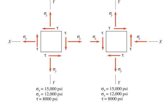
Chapter 17, Problem 17.18P
Stresses developed at a point in a machine part are shown acting on infinitesimal elements. For each element, calculate
(a) the normal and shear stress intensities on a plane, the normal of which is inclined at an angle of
(b) the principal stresses and the orientation of the principal planes
(c) the maximum shear stress
Expert Solution & Answer
Want to see the full answer?
Check out a sample textbook solution
Students have asked these similar questions
At a point in a piece of elastic material there are three mutually perpendicular planes on which the stresses are as follows : tensile stress 50 N/mm2, shear stress 40 N/mm2 on plane, compressive stress 35 N/mm2 and complementary shear stress 40 N/mm2 on the second plane, no stress on the third plane. Find (a) the principal stresses and the positions of the plane on which they act (b) the position of the planes on which there is no normal stress.
The principal tensile stress at a point across two mutually perpendicular planes are 100 N/mm2 and 40 N/mm2. The normal, tangential and resultant stresses on a plane inclined at 20° to the axis of the minor principal stress by analytical method is
The stresses acting on element A in the web of a train rail are found to be 'X (MPa)'
tension in the horizontal x-direction and 'Y (MPa)' compression in the vertical
y-direction. Also, shear stresses of magnitude 'S (MPa)' act in the directions shown in
the figure.
Draw Mohr's circle for the state of stress.
Determine the stresses (Ox', Oy' and Txy') acting on an element oriented at an angle
'D' from the horizontal Show these stresses on a sketch of an element oriented at this angle
X=45MPA,Y=150MPA,S=52MPA,D=-40 Degree
Chapter 17 Solutions
Applied Statics and Strength of Materials (6th Edition)
Ch. 17 - Prob. 17.1PCh. 17 - A horizontal 30-ft simple span beam is supported...Ch. 17 - A 1-in.-by-4-in, steel bar is subjected to the...Ch. 17 - A W410100 structural steel wide-flange section is...Ch. 17 - A W1272 structural steel wide-flange section is...Ch. 17 - A solid steel shaft 3 in. in diameter and 4 ft...Ch. 17 - A short compression member is subjected to a...Ch. 17 - With reference to Problem 17.7, calculate the...Ch. 17 - A section of a 51-mm-diameter standard-weight...Ch. 17 - For the pipe of Problem 17.9, compute the maximum...
Ch. 17 - A concrete pedestal is in the shape of a cube and...Ch. 17 - 17.12 For the pedestal of Problem 17.11, assume...Ch. 17 - 17.13 Rework Problem 17.11, but assume that the...Ch. 17 - A 12-in-square concrete pedestal is subjected to a...Ch. 17 - 17.15 A short compression member is subjected to a...Ch. 17 - A rectangular concrete footing, 4 ft by 8 ft in...Ch. 17 - The bending and shear stresses developed at a...Ch. 17 - Stresses developed at a point in a machine part...Ch. 17 - Calculate the principal stresses at points A and B...Ch. 17 - 17.20 Rework Problem 17.19 using P = 8000 lb and...Ch. 17 - 17.21 A 1-in.-square steel bar is subjected to an...Ch. 17 - 17.22 A bar having a cross-sectional area of 6...Ch. 17 - Rework Problem 17.22, changing the load to a...Ch. 17 - Solve Problem l7.17 using Mohr’s circle.Ch. 17 - For the elements shown in Problem 17.18, use...Ch. 17 - Solve Problem 17.19 using Mohr’s circle.Ch. 17 - In Problem 17.19, change the load to 8000 lb and...Ch. 17 - For the following computer problems, any...Ch. 17 - For the following computer problems, any...Ch. 17 - For the following computer problems, any...Ch. 17 - For the following computer problems, any...Ch. 17 - A 4-in.-by-8-in. (S4S) Douglas fir timber beam is...Ch. 17 - A horizontal flexural member (a girt) in the wall...Ch. 17 - A simply supported W1850 structural steel...Ch. 17 - A steel link in a machine is designed to avoid...Ch. 17 - 17.36 An 8-in-square (S4S) vertical timber post is...Ch. 17 - A short 3-in.-square steel bar with a...Ch. 17 - A timber member 150 mm by 250 mm (S4S) is loaded...Ch. 17 - A concrete wall 8 ft high and 3 ft thick is...Ch. 17 - 17.40 A short compression member is subjected to a...Ch. 17 - 17.41 Calculate the maximum eccentric load that...Ch. 17 - A short compression member is subjected to two...Ch. 17 - 17.43 Calculate the force P that may be applied to...Ch. 17 - 17.44 A load of 1000 lb is supported on a...Ch. 17 - 17.45 A short compression member is subjected to...Ch. 17 - 17.46 A structural steel wide-flange section is...Ch. 17 - 17.47 A cast-iron frame for a piece of industrial...Ch. 17 - 17.48 The assembly shown is used in a machine. It...Ch. 17 - 17.49 A 50-mm-diameter solid steel shaft is...Ch. 17 - An element of a machine member is subjected to the...Ch. 17 - 17.51 A short-span cantilever built-up beam has...Ch. 17 - Solve Problem 17.50 using Mohr’s circle.Ch. 17 - 17.53 A cantilever beam is subjected to an...Ch. 17 - A 6-in.-diameter solid shaft is subjected to a...Ch. 17 - Rework parts (b) and (c) of Example 17.7 using...
Knowledge Booster


Learn more about
Need a deep-dive on the concept behind this application? Look no further. Learn more about this topic, mechanical-engineering and related others by exploring similar questions and additional content below.Similar questions
- An clement m plane stress from the frame of a racing car is oriented at a known angle 8 (sec figure). On this inclined clement, the normal and shear stresses have the magnitudes and directions shown in the figure. Determine the normal and shear stresses acting on an clement whose sides are parallel to the \y axes, that is, determine crv, tr(_, and t, Show the results on a sketch of an clement oriented at B .arrow_forward-18 through 7.4-25 An clement in plane stress is subjected to stresses a,, ay., and axy. (see figure). Using Mohr’s circle, determine (a) the principal stresses and (b) the maximum shear stresses and associated normal stresses. Show all results on sketches of properly oriented elements.arrow_forward-18 through 7.4-25 An clement in plane stress is subjected to stresses sx,,sy., andtxy(see figure). Using Mohr’s circle, determine (a) the principal stresses and (b) the maximum shear stresses and associated normal stresses. Show all results on sketches of properly oriented elements.arrow_forward
- -26 A rectangular plate of dimensions 125 mm × 75 mm is subjected to tensile stress sy= 67 kPa and compressive stress a. If it is known that the normal stress along the diagonal t—t is ??t= -6.57 kPa, find stress ??y on element A. aarrow_forward.4-2 An element in uniaxial stress is subjected to tensile stresses sx= 57 MPa. as shown in the figure. Using Mohr’s circle, determine the following. (a) The stresses acting on an clement oriented at an angle 0 = 33° from the x axis (minus means clockwise). (b) The maximum shear stresses and associated normal stresses. Show all results on sketches of properly oriented elements.arrow_forwardThe stresses acting on an element are x= 750 psi, y= 600 psi, and xy = 400 psi. Determine the principal stresses and show them on a sketch of a properly oriented element.arrow_forward
- At a point on the surface of an elliptical exercise machine, the material is in biaxial stress with t = 1400 psi and trv = —900 psi, as shown in the figure part a. The figure part b shows an inclined plane aa cut through the same point in the material but oriented at an angle ft Determine the value of the angle 6 between zero and 90° such that no normal stress acts on plane aa. Sketch a stress clement having plane aa as one of its sides and show all stresses acting on the clementarrow_forwardSolve the preceding problem for an element in plane stress on the bottom surface of a fuel tanker (figure part a); stresses are sx= 105 MPa, sy. = 75 MPa, and ??xy= 25 MPa. Determine the stresses acting on an element oriented at an angle ?? = 40° from the x axis, where the angle is positive when counterclockwise. Show these stresses on a sketch of an element oriented at the angle ??.arrow_forward2. At a point in a brocket, the stresses on two mutually perpendicular planes are 180 MN/m? (tensile) and 70 MN/m2 (Compressive). The shear stress across the planes is 65 MN/m2. Find the following by Mohr's Circle method and compare with Analytical solutions: (i)The Normal stress on a plane making an angle of 50° with the plane of first stress. (ii)Shear stress on the plane (iii) Maximum shear stress (iv) Resultant stress and it's direction. (v) Major and minor principal stresses.arrow_forward
- The normal and shear stresses acting on one plane passing through a point in a soil mass are 120 psi compression and 25 psi, respectively. On an orthogonal plane, the respective stresses are 40 psi compression and 25 psi. (a) Draw the Mohr’s circle for this stress condition. (b) What are the principal stresses? (c) Determine the angle between the plane on which the 120 psi stress acts and the major principal plane. (d) What is the maximum shear stress acting at the point?arrow_forwardDirect stresses of 120 N/mm2 (tension) and 90 N/mm2 (compression) are applied at a particular point in an elastic material on two mutually perpendicular planes. The principal stress in the material is limited to 200 N/mm2 (tension). Calculate the allowable value of shear stress at the point on the given planes. Determine also the value of the other principal stress and the maximum value of shear stress at the point using Mohr’s Circle.arrow_forwardProblem 2: A state of plane stress at a point on the surface of a structure consists of the following stress components: Ox = 18 ksi, oy = 24 ksi, and Txy = 15 ksi. Note that the stress components act in the directions shown on the element below. Ox Txy 24 ksi бу 18 ksi 15 ksi (a) Draw a complete Mohr's circle for this stress state. Clearly label the X and Y faces, the center C, and the radius R. (b) Using Mohr's circle, determine the stress components Ox, Oy, and Txy on an element rotated 25° counter-clockwise from the original element shown. Label all of these quantities on the circle. (c) Show all stresses from part (b) on a properly oriented stress element. Be sure to include all stress components acting on the element.arrow_forward
arrow_back_ios
SEE MORE QUESTIONS
arrow_forward_ios
Recommended textbooks for you
 Mechanics of Materials (MindTap Course List)Mechanical EngineeringISBN:9781337093347Author:Barry J. Goodno, James M. GerePublisher:Cengage Learning
Mechanics of Materials (MindTap Course List)
Mechanical Engineering
ISBN:9781337093347
Author:Barry J. Goodno, James M. Gere
Publisher:Cengage Learning
Understanding Stress Transformation and Mohr's Circle; Author: The Efficient Engineer;https://www.youtube.com/watch?v=_DH3546mSCM;License: Standard youtube license