
Applied Statics and Strength of Materials (6th Edition)
6th Edition
ISBN: 9780133840544
Author: George F. Limbrunner, Craig D'Allaird, Leonard Spiegel
Publisher: PEARSON
expand_more
expand_more
format_list_bulleted
Concept explainers
Videos
Textbook Question
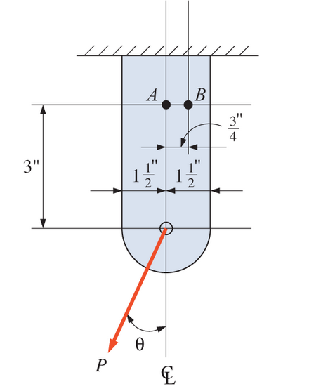
Chapter 17, Problem 17.19P
Calculate the principal stresses at points A and B for the bracket shown. P = 9000 lb and

Expert Solution & Answer

Trending nowThis is a popular solution!

Students have asked these similar questions
Determine the principal stresses at points A and B of the cylinder. Consider: L = 70 mm; d = 20 mm; F = 12 kN; P = 15 kN; T = 800 Nm.
Two solid cylindrical rods (1) and (2) are joined together at flange B and loaded, as shown. The diameter of rod (1) is d1 = 1.66 in. and the diameter of rod (2) is d2 = 2.68 in. Determine the normal stresses in rods (1) and (2). Assume P = 17 kips and Q = 29 kips. Use positive for tensile stress and negative for compressive stress.
5. Segment AB of the bar is a tube with an
outer diameter of d1 and a wall thickness of
0.125 in. Segment BC is a solid rod of
diameter d2. The average normal stresses
must not exceed 3400 psi in rod AB and 6500
in rod BC, respectively. Use P1 = 3,600 lb. and
P2 = 5,500 lb.
0.125 in.
di
В
A
6 in.-
6 in.
Determine the smallest allowable value of d1
(in inches). Round-off to 2-decimal places.
Your answer
Determine the smallest allowable value of d2
(in inches). Round-off to 2-decimal places.
Your answer
Вack
Next
Clear form
Never submit pas swords through G0ogle Forms
Chapter 17 Solutions
Applied Statics and Strength of Materials (6th Edition)
Ch. 17 - Prob. 17.1PCh. 17 - A horizontal 30-ft simple span beam is supported...Ch. 17 - A 1-in.-by-4-in, steel bar is subjected to the...Ch. 17 - A W410100 structural steel wide-flange section is...Ch. 17 - A W1272 structural steel wide-flange section is...Ch. 17 - A solid steel shaft 3 in. in diameter and 4 ft...Ch. 17 - A short compression member is subjected to a...Ch. 17 - With reference to Problem 17.7, calculate the...Ch. 17 - A section of a 51-mm-diameter standard-weight...Ch. 17 - For the pipe of Problem 17.9, compute the maximum...
Ch. 17 - A concrete pedestal is in the shape of a cube and...Ch. 17 - 17.12 For the pedestal of Problem 17.11, assume...Ch. 17 - 17.13 Rework Problem 17.11, but assume that the...Ch. 17 - A 12-in-square concrete pedestal is subjected to a...Ch. 17 - 17.15 A short compression member is subjected to a...Ch. 17 - A rectangular concrete footing, 4 ft by 8 ft in...Ch. 17 - The bending and shear stresses developed at a...Ch. 17 - Stresses developed at a point in a machine part...Ch. 17 - Calculate the principal stresses at points A and B...Ch. 17 - 17.20 Rework Problem 17.19 using P = 8000 lb and...Ch. 17 - 17.21 A 1-in.-square steel bar is subjected to an...Ch. 17 - 17.22 A bar having a cross-sectional area of 6...Ch. 17 - Rework Problem 17.22, changing the load to a...Ch. 17 - Solve Problem l7.17 using Mohr’s circle.Ch. 17 - For the elements shown in Problem 17.18, use...Ch. 17 - Solve Problem 17.19 using Mohr’s circle.Ch. 17 - In Problem 17.19, change the load to 8000 lb and...Ch. 17 - For the following computer problems, any...Ch. 17 - For the following computer problems, any...Ch. 17 - For the following computer problems, any...Ch. 17 - For the following computer problems, any...Ch. 17 - A 4-in.-by-8-in. (S4S) Douglas fir timber beam is...Ch. 17 - A horizontal flexural member (a girt) in the wall...Ch. 17 - A simply supported W1850 structural steel...Ch. 17 - A steel link in a machine is designed to avoid...Ch. 17 - 17.36 An 8-in-square (S4S) vertical timber post is...Ch. 17 - A short 3-in.-square steel bar with a...Ch. 17 - A timber member 150 mm by 250 mm (S4S) is loaded...Ch. 17 - A concrete wall 8 ft high and 3 ft thick is...Ch. 17 - 17.40 A short compression member is subjected to a...Ch. 17 - 17.41 Calculate the maximum eccentric load that...Ch. 17 - A short compression member is subjected to two...Ch. 17 - 17.43 Calculate the force P that may be applied to...Ch. 17 - 17.44 A load of 1000 lb is supported on a...Ch. 17 - 17.45 A short compression member is subjected to...Ch. 17 - 17.46 A structural steel wide-flange section is...Ch. 17 - 17.47 A cast-iron frame for a piece of industrial...Ch. 17 - 17.48 The assembly shown is used in a machine. It...Ch. 17 - 17.49 A 50-mm-diameter solid steel shaft is...Ch. 17 - An element of a machine member is subjected to the...Ch. 17 - 17.51 A short-span cantilever built-up beam has...Ch. 17 - Solve Problem 17.50 using Mohr’s circle.Ch. 17 - 17.53 A cantilever beam is subjected to an...Ch. 17 - A 6-in.-diameter solid shaft is subjected to a...Ch. 17 - Rework parts (b) and (c) of Example 17.7 using...
Knowledge Booster


Learn more about
Need a deep-dive on the concept behind this application? Look no further. Learn more about this topic, mechanical-engineering and related others by exploring similar questions and additional content below.Similar questions
- A thin cylinder of inner radius 500 mm and thickness 10 mm subjected to an internal pressure of 5 MPa. The average circumferential (hoop) stress in MPa isarrow_forwardA cylinder of (320) mm inside diameter and (64) mm thickness is subjected to an internal pressure of 15 MPa. Find the variation of circumferential and radial stresses in the shell and plot them. What is the increase in the inside and outside diameters of the shell? Take E=200 GPa and v=0.3arrow_forwardA machine component is fabricated from a bent tube as shown below. One part of the tube lies along the z- axis, and the other part is parallel to the y-axis. The outside diameter of the tube is do 122 mm and its inside diameter is dį = 108 mm. A force F = 8.5 kN acts along a line from point to point D. Determine the principal stresses and the absolute maximum shear stresses at points A and B. Note that point A lies along the y-axis and point Blies along the x-axis. Given: • L₁ 258 mm L₂ = 118 mm • L -281 mm LA-602 mm 4 P (α₂₁)A- (₁2) A (Tmax) A L2 Z ²1 00 B L₁7 number (rtol=0,01, atol=1e-05) number (rtol-0.01, atol-1e-05) number (rtol-0.01 atol-le-057 F 0 MPA LA D L3 y 0 0arrow_forward
- 7. Determine the stress developed in the Tensional Cord given that the cable's diameter is 0.6 inches and the bar weigh 6kips. Figure P-106 3 m 5 m 5 m Earrow_forwardThe uniform 300-lb bar AB carries a 500-lb vertical force at A. The bar is supported by a pin at B and the 0:5-in. diameter cable CD. Find the stress in the cable. 4 ft A 3 ft 3 ft B. 500 Ibarrow_forwardTwo blocks joined by a single pin are subjected to a pulling force of P = 250 Ib. The pin has a diameter of 0.25 in and the dimensions of the blocks with respect to the figure below are listed below. a = 2.42 in b = 1.52 in C = 1.5 in ti = 0.89 in t2 = 1.2 in Note that the dimensions b and c represent the distance from the edge of the block to the middle of the pin t, 1 a Vinter201920-Engr220-001/images/9de8f780-b478-3fb6-91f7-bd1015381538_fafc4bb4-e5d Image is not drawn to scale.arrow_forward
- 1. A 60-mm diameter steel tube with a wall thickness of 3 mm just fits in a rigid hole. Determine the tangential stress developed if an axial compressive load of 12 kN is applied. Use v = 0.30 and E = 200 GPa. Answer: 0 = 6.37 MPa 2. A 200-mm long bronze tube closed at both ends fits without clearance in a 70-mm hole in a rigid block. It has a diameter of 70 mm and a wall thickness of 5 mm. The tube then sustained an internal pressure of 4.5 MPa. Use v = 0.33 and E= 83 GPa. Compute the tangential stress in the tube. Answer: Ot = 5.20 MPaarrow_forwardDetermine the stresses at points A and B as a results of applying each of the following internal loads N = 300 N, V = 250 N, M = 120 N.m and T = 300 N/m. The diameter is 20 mm. You must show your detailed solutionsarrow_forwardThe U-bar shown below has a circular cross section with a diameter of 1 in. For the loading shown, determine the maximum and minimum normal stresses on a cross section between A and B. 500 lb- A B 2₁ 4 in 500 lbarrow_forward
- Find the Principal Stresses on the tube below given the forces in the X,Y and Z axis shown below: Radius: R2=5mm R1=4mm and τxy= 0.1 Paarrow_forwardA force of 120 lb is applied to the edge of the member shown in the figure below. Neglect the weight of the member and determine the state of stress at points B and C using the superposition. 120 lb 4.5 in. | 4.5 in. -2.5 in 2.5 in B-arrow_forward800 N 120 N.m d = 8 cm 600 N Q /If the cross section of the femur can be approximated as a circular tube, determine the state of stresses on the 160 N.m points A and B at section due to the loads as shown in figure. T. = 22 mm n = 18 mm tu Sl'o = Iarrow_forward
arrow_back_ios
SEE MORE QUESTIONS
arrow_forward_ios
Recommended textbooks for you
 Elements Of ElectromagneticsMechanical EngineeringISBN:9780190698614Author:Sadiku, Matthew N. O.Publisher:Oxford University Press
 Mechanics of Materials (10th Edition)Mechanical EngineeringISBN:9780134319650Author:Russell C. HibbelerPublisher:PEARSON
 Thermodynamics: An Engineering ApproachMechanical EngineeringISBN:9781259822674Author:Yunus A. Cengel Dr., Michael A. BolesPublisher:McGraw-Hill Education
 Control Systems EngineeringMechanical EngineeringISBN:9781118170519Author:Norman S. NisePublisher:WILEY
 Mechanics of Materials (MindTap Course List)Mechanical EngineeringISBN:9781337093347Author:Barry J. Goodno, James M. GerePublisher:Cengage Learning
 Engineering Mechanics: StaticsMechanical EngineeringISBN:9781118807330Author:James L. Meriam, L. G. Kraige, J. N. BoltonPublisher:WILEY
Elements Of Electromagnetics
Mechanical Engineering
ISBN:9780190698614
Author:Sadiku, Matthew N. O.
Publisher:Oxford University Press
Mechanics of Materials (10th Edition)
Mechanical Engineering
ISBN:9780134319650
Author:Russell C. Hibbeler
Publisher:PEARSON
Thermodynamics: An Engineering Approach
Mechanical Engineering
ISBN:9781259822674
Author:Yunus A. Cengel Dr., Michael A. Boles
Publisher:McGraw-Hill Education
Control Systems Engineering
Mechanical Engineering
ISBN:9781118170519
Author:Norman S. Nise
Publisher:WILEY
Mechanics of Materials (MindTap Course List)
Mechanical Engineering
ISBN:9781337093347
Author:Barry J. Goodno, James M. Gere
Publisher:Cengage Learning
Engineering Mechanics: Statics
Mechanical Engineering
ISBN:9781118807330
Author:James L. Meriam, L. G. Kraige, J. N. Bolton
Publisher:WILEY
Everything About COMBINED LOADING in 10 Minutes! Mechanics of Materials; Author: Less Boring Lectures;https://www.youtube.com/watch?v=N-PlI900hSg;License: Standard youtube license