
Applied Statics and Strength of Materials (6th Edition)
6th Edition
ISBN: 9780133840544
Author: George F. Limbrunner, Craig D'Allaird, Leonard Spiegel
Publisher: PEARSON
expand_more
expand_more
format_list_bulleted
Videos
Textbook Question
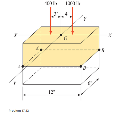
Chapter 17, Problem 17.42SP
A short compression member is subjected to two compressive loads, as shown. The member is 6 in. by 12 in. in cross section. Calculate the combined stress at outer edges AA and BB.
Expert Solution & Answer
Want to see the full answer?
Check out a sample textbook solution
Students have asked these similar questions
The vertical load P acting on the wheel of a traveling crane is 13,000 lb. What is the average shear stress in the 1.25 in. diameter axle?
A circular tube AB is fixed at one end and free at the other end. The tubeis subjected to axialforce at joint B. If the outer diameter of the tube is 3 in, and thethickness is 3/4 in., calculate the maximum normal stress in the tube
For the ring and the load applied. Calculate the normal stresses at point A and B.
Hint: Normal stresses are due to both the normal force and the bending moment calculated for curved beams.
Chapter 17 Solutions
Applied Statics and Strength of Materials (6th Edition)
Ch. 17 - Prob. 17.1PCh. 17 - A horizontal 30-ft simple span beam is supported...Ch. 17 - A 1-in.-by-4-in, steel bar is subjected to the...Ch. 17 - A W410100 structural steel wide-flange section is...Ch. 17 - A W1272 structural steel wide-flange section is...Ch. 17 - A solid steel shaft 3 in. in diameter and 4 ft...Ch. 17 - A short compression member is subjected to a...Ch. 17 - With reference to Problem 17.7, calculate the...Ch. 17 - A section of a 51-mm-diameter standard-weight...Ch. 17 - For the pipe of Problem 17.9, compute the maximum...
Ch. 17 - A concrete pedestal is in the shape of a cube and...Ch. 17 - 17.12 For the pedestal of Problem 17.11, assume...Ch. 17 - 17.13 Rework Problem 17.11, but assume that the...Ch. 17 - A 12-in-square concrete pedestal is subjected to a...Ch. 17 - 17.15 A short compression member is subjected to a...Ch. 17 - A rectangular concrete footing, 4 ft by 8 ft in...Ch. 17 - The bending and shear stresses developed at a...Ch. 17 - Stresses developed at a point in a machine part...Ch. 17 - Calculate the principal stresses at points A and B...Ch. 17 - 17.20 Rework Problem 17.19 using P = 8000 lb and...Ch. 17 - 17.21 A 1-in.-square steel bar is subjected to an...Ch. 17 - 17.22 A bar having a cross-sectional area of 6...Ch. 17 - Rework Problem 17.22, changing the load to a...Ch. 17 - Solve Problem l7.17 using Mohr’s circle.Ch. 17 - For the elements shown in Problem 17.18, use...Ch. 17 - Solve Problem 17.19 using Mohr’s circle.Ch. 17 - In Problem 17.19, change the load to 8000 lb and...Ch. 17 - For the following computer problems, any...Ch. 17 - For the following computer problems, any...Ch. 17 - For the following computer problems, any...Ch. 17 - For the following computer problems, any...Ch. 17 - A 4-in.-by-8-in. (S4S) Douglas fir timber beam is...Ch. 17 - A horizontal flexural member (a girt) in the wall...Ch. 17 - A simply supported W1850 structural steel...Ch. 17 - A steel link in a machine is designed to avoid...Ch. 17 - 17.36 An 8-in-square (S4S) vertical timber post is...Ch. 17 - A short 3-in.-square steel bar with a...Ch. 17 - A timber member 150 mm by 250 mm (S4S) is loaded...Ch. 17 - A concrete wall 8 ft high and 3 ft thick is...Ch. 17 - 17.40 A short compression member is subjected to a...Ch. 17 - 17.41 Calculate the maximum eccentric load that...Ch. 17 - A short compression member is subjected to two...Ch. 17 - 17.43 Calculate the force P that may be applied to...Ch. 17 - 17.44 A load of 1000 lb is supported on a...Ch. 17 - 17.45 A short compression member is subjected to...Ch. 17 - 17.46 A structural steel wide-flange section is...Ch. 17 - 17.47 A cast-iron frame for a piece of industrial...Ch. 17 - 17.48 The assembly shown is used in a machine. It...Ch. 17 - 17.49 A 50-mm-diameter solid steel shaft is...Ch. 17 - An element of a machine member is subjected to the...Ch. 17 - 17.51 A short-span cantilever built-up beam has...Ch. 17 - Solve Problem 17.50 using Mohr’s circle.Ch. 17 - 17.53 A cantilever beam is subjected to an...Ch. 17 - A 6-in.-diameter solid shaft is subjected to a...Ch. 17 - Rework parts (b) and (c) of Example 17.7 using...
Knowledge Booster


Learn more about
Need a deep-dive on the concept behind this application? Look no further. Learn more about this topic, mechanical-engineering and related others by exploring similar questions and additional content below.Similar questions
- Given the section is subjected to a moment of 500 N-m, calculate the normal stress in MPa at the bottom of the section. Use positive for tension and negative for compression. 10 mm 30 mm 10 mm 30 mmarrow_forwardcircular tube AB is fixed at one end andfree at the other end. The tube is subjected to axialforce at joint B. If the outer diameter of the tube is 75 mm and the thickness is 19 mm, calculate the max-imum normal stress in the tube.arrow_forwardIn the figure shown if the applied force F= 24KN. Compute the stress, in MPa, in member BD.arrow_forward
- The cross section of a reinforced concrete beam is shown below. It has a modular ratio of 15. If the allowable compressive stress in the concrete is 6 MPa and the allowable tensile stress in the steel is 120 MPa, determine diameter of the three reinforcing steel rods to make the beam an economic section.arrow_forwardDetermine the stress in member KE for the truss loaded and supported as shown in figure (2). Note use the section method, the cross-section area of member KE is 917 mm? 150 Ib 6' 6' 6' 6' F 6' 8' 250 Ib 6' 8' Fig.2. Q2 inarrow_forwardTo avoid interference, a link in a machine is designed so that its cross-sectional area is reduced one half at section A-B as shown below. If the thickness of the link is 50 mm, compute the maximum force P that can be applied if the maximum normal stress on section A-B is limited to 80 MPa.arrow_forward
- The figure below shows a simply supported prismatic beam with an applied uniform load. The labeled points A through E are equally spaced (at the quarter points) along the length of the beam and are located at the top of the beam section. Points A and E may be assumed to be located directly above the supports. Rank the points, from greatest to least, on the basis of the absolute value of normal stress in the beam section.arrow_forwardThe cross-sectional area of each member of the truss is 1200 mm2. Calculate the stresses in members DF, CE, and BD. The truss is pin-supported at A and roller-supported at F. draw free-body diagramarrow_forwardA bar having a cross-section areas of 700mm2 is subjected to axial loads at the positions indicated,find the value of stress in the segment QRarrow_forward
- A force Q is applied to a rectangular member with a size of 300mm x 450mm. Q is located 37.5mm left and 60mm north of the center of gravity and induces a stress of 1.75 MPa compression at point A. What is the stress induced at point C & D in MPaarrow_forwardThe screw of the clamp exerts a compressive force of 500 lb on the woodblocks. Sketch the stress distribution along section a–a of the clamp. The cross section is rectangular, 0.75 in. by 0.50 in.arrow_forwardModule 4 Stress Distribution Point loads of 2000, 4000, and 6000 Ibs act at points A, B and C respectively, as shown below. Determine the increase in vertical stress at a depth of 10 feet below point D. A 10 feet B 10 feet C feet Darrow_forward
arrow_back_ios
SEE MORE QUESTIONS
arrow_forward_ios
Recommended textbooks for you
 Elements Of ElectromagneticsMechanical EngineeringISBN:9780190698614Author:Sadiku, Matthew N. O.Publisher:Oxford University Press
 Mechanics of Materials (10th Edition)Mechanical EngineeringISBN:9780134319650Author:Russell C. HibbelerPublisher:PEARSON
 Thermodynamics: An Engineering ApproachMechanical EngineeringISBN:9781259822674Author:Yunus A. Cengel Dr., Michael A. BolesPublisher:McGraw-Hill Education
 Control Systems EngineeringMechanical EngineeringISBN:9781118170519Author:Norman S. NisePublisher:WILEY
 Mechanics of Materials (MindTap Course List)Mechanical EngineeringISBN:9781337093347Author:Barry J. Goodno, James M. GerePublisher:Cengage Learning
 Engineering Mechanics: StaticsMechanical EngineeringISBN:9781118807330Author:James L. Meriam, L. G. Kraige, J. N. BoltonPublisher:WILEY
Elements Of Electromagnetics
Mechanical Engineering
ISBN:9780190698614
Author:Sadiku, Matthew N. O.
Publisher:Oxford University Press
Mechanics of Materials (10th Edition)
Mechanical Engineering
ISBN:9780134319650
Author:Russell C. Hibbeler
Publisher:PEARSON
Thermodynamics: An Engineering Approach
Mechanical Engineering
ISBN:9781259822674
Author:Yunus A. Cengel Dr., Michael A. Boles
Publisher:McGraw-Hill Education
Control Systems Engineering
Mechanical Engineering
ISBN:9781118170519
Author:Norman S. Nise
Publisher:WILEY
Mechanics of Materials (MindTap Course List)
Mechanical Engineering
ISBN:9781337093347
Author:Barry J. Goodno, James M. Gere
Publisher:Cengage Learning
Engineering Mechanics: Statics
Mechanical Engineering
ISBN:9781118807330
Author:James L. Meriam, L. G. Kraige, J. N. Bolton
Publisher:WILEY
Mechanics of Materials Lecture: Beam Design; Author: UWMC Engineering;https://www.youtube.com/watch?v=-wVs5pvQPm4;License: Standard Youtube License