
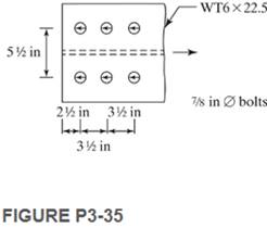
Determine the LRFD design strength and the ASD allowable strength of the sections given, including block shear.
3-35. A

Learn your wayIncludes step-by-step video

Chapter 3 Solutions
Structural Steel Design (6th Edition)
Additional Engineering Textbook Solutions
Foundation Design: Principles and Practices (3rd Edition)
Structural Analysis (10th Edition)
Materials for Civil and Construction Engineers (4th Edition)
Elementary Surveying: An Introduction To Geomatics (15th Edition)
Elementary Surveying (14th Edition)
Starting Out with Java: From Control Structures through Data Structures (4th Edition) (What's New in Computer Science)

- The built-up girder below is comprised of four A572 Grade 50 plates welded together. Compute the section modulus (S), plastic modulus (Z₁), and shape factor (Z₁/S). Using Table B41.b of the Specification, determine whether the flanges and web are compact, noncompact, or slender. -PL 1" x 40" 10" CLEAR SPACING PL 1.5" x 20" TYParrow_forwardDetermine the controlling (lowest) net area of the member. X = 2.69 Y = (6-2.69)/2 Z=0.7 Y" -X Y" 5 @ 1/2" OD O a Do -OHD -(5)-z" bolts -L6 X 4 X 7/16arrow_forward... A36 (Fy=36ksi; Fu=58ksi) steel is used for the tension member shown. a. Determine the design strength based on the gross area. b. Determine the design strength based on the net area. - PL % x12 2" 5/8" 2" 4" 12" 4" 2" 4-in.-diameter bolts Cross Sectional area of PL3/8x6 a) Blank 1 b) Blank 2 Blank 1 Add your answer Blank 2 Add your answerarrow_forward
- (See Attached picture of truss) 2. Since the reaction force at point A is 8975 #, The reaction force at point H is 7625#, the stress force in member AB is 14262 # (C), and the stress force in member BC is 11083# (T); calculate the minimum steel bolt size for attachment at points A and H. Use a factor of safety of 1.5 and a fitting factor of 1.15arrow_forwardThe following image shows a front and side view of the column connection. The bolts have a diameter of ¾”. The W12X65 profile has a thickness of 0.605”. Determine: a. The shear stress in the bolts. Answ. 11.81 ksi b. The axial stress in the bolts. Answ. 23.62 ksi c. The support stress in the W12X65 profile. 11.50 ksiarrow_forwardBottom chord of truss is composed of two angle bars each having a dimension of 185 mm x 146 mm x 8.7 mm. Between them is a gusset plate, 9.5mm thick. At each end of joints, four 19mm-dia. bolts are fastened along the gage line, having an edge distance of 44 mm and 59mm pitch. Use A36 steel Fy 248 MPa Fu = 400 MPa %3D spacing of bolt = 68.9 mm %3D 9 5mm thick gunset plate edge dist Compute the capacity of the bottom chord based on block shear strength, in KN. uadarrow_forward
- 3.5-1 Block Shear The tension member is a PL¾8 X 5¹2 of A242 steel. It is connected to a 38-in. thick gusset plate, also of A242 steel, with ¾-inch diameter bolts as shown in Figure P3.5-1. Determine the nominal block shear strength of the tension member. 1½" ro 2¹2" O 1 1½" I 1½" 3" O O O o FIGURE P3.5-1 O- 14 3" 1½" 3.5-1 the shear areas are Agv = (3/8) (7.5) 2 5. 625 in. ² and, since there are 2.5 hole diameters in each line of bolts, Any (3/8) [7.5-2.5(3/4+1/8)] x 2 = 3.984 in.² The tension area is Ant = (3/8) [2.5-1(7/8)] = 0.6094 in. ²2 Fy= 50 ksi, Fu = 70 ksi Rn 0.6FuAny + Ubs FuAnt = = 0.6(70) (3.984) + 1.0(70) (0.6094) = 210 kips Check upper limit: 0.6FyAgv + UbsFuAnt = 0.6(50)(5.625) + 1.0(70)(0.6094) = 211 kips > 210 kipsarrow_forwardPLATE NO 3 Method of Sections Chapter 5 Problem 5-2 Page 76 Using the method of sections, determine the kind and amount of stress in the following members of the truss shown in figure P5-2 (page 76). U:U2 UıL2 LIL2 U2U3 U2L3 L2L3 1000lb 1000lb U3 1000lb 1000lb 1000lb U2 U4 500lb Ui 500lb h=20ft Us Lo L1 L2 L3 L4 Ls RAV 6 panels at 10' = 60 ft RBvarrow_forward1. A double-angle tension member, 2L 3 × 2 × 3/16 LLBB, of A36 steel is subjected to a dead load of 12 kips and a live load of 36 kips. It is connected to a gusset plate with 3/4- inch-diameter bolts through the long legs. Does this member have enough strength? Assume that Ae = 0.85An. a. ASD b. LRFD Section 1 (T COIC.:)arrow_forward
- Determine the LRFD design tensile strength of the bolted connection shown. The angles are connected through the longer legs to a % x 11 in plate. Holes are made for % in bolts. Use steel F,-50 ksi F-65 ksi. L5x3x% (4, = 4.92in, x%30.947in, y=1.69in). Consider block shear in your calculations. %3D 3/4" plate 2L5 x 3 % x 5/8 3" Pr 3" 3 @ 3" 12" - 3" P,arrow_forwardA W16 x 45 of A992 steel is connected to a plate at each flange as shown. Determine the nominal strength based on the net section using alternative value of shear lag factor. * -2¼" 8-in.-diameter bolts W16 x 45arrow_forwardProblem 1 Given the double splice connection shown made up of 6mm x 150mm steel plates with double row of 19mm diameter bolts. O = 552.93 MPa , t= 207MPA and op = 552.93 MPa a. Compute the tensile force of the steel plates ANS b. Compute the number of 19mm diameter bolts from shear ANS c. Compute the number of 19mm diameter bolts from bearing ANS d. Compute the number of 19mm diameter bolts for the connection ANS 150mm 6mmarrow_forward
 Steel Design (Activate Learning with these NEW ti...Civil EngineeringISBN:9781337094740Author:Segui, William T.Publisher:Cengage Learning