
Applied Statics and Strength of Materials (6th Edition)
6th Edition
ISBN: 9780133840544
Author: George F. Limbrunner, Craig D'Allaird, Leonard Spiegel
Publisher: PEARSON
expand_more
expand_more
format_list_bulleted
Videos
Textbook Question
Chapter 17, Problem 17.32SP
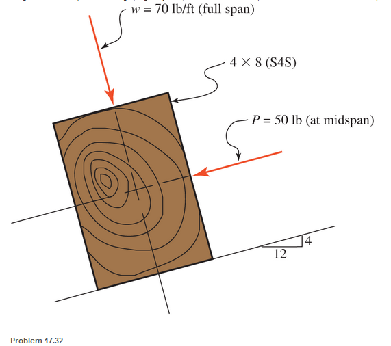
A 4-in.-by-8-in. (S4S) Douglas fir timber beam is supported on a 16-ft simple span and is subjected to the loads shown. The uniformly distributed line load does not include the weight of the beam (the beam weight. a gravity load, should be considered). Find the maximum tensile and compressive stresses.
Expert Solution & Answer
Want to see the full answer?
Check out a sample textbook solution
Students have asked these similar questions
A steel beam of I cross-section is simply supported on a span of 4m. Find the safe uniformly distributed load the beam can carry if the tensile stress is not to exceed 26 N/mm2. Also find the maximum compressive stress.
A beam of rectangular cross-section is 64 mm broad, 100 mm deep, and 1.6 m long. It is simply supported at each end and carries a concentrated load of 10 kN at its mid-length. Neglecting the weight of the beam, find the maximum stress in the material.
Calculate the end bearing length (in.) required for a 10-in.-by-16-in. timber beam (dressed) that is supported on a reinforced concrete wall as shown. The beam reaction is 18,000 lb and the allowable compressive stress perpendicular to the grain for the timer member is 400 psi. (Unit: in.)
Chapter 17 Solutions
Applied Statics and Strength of Materials (6th Edition)
Ch. 17 - Prob. 17.1PCh. 17 - A horizontal 30-ft simple span beam is supported...Ch. 17 - A 1-in.-by-4-in, steel bar is subjected to the...Ch. 17 - A W410100 structural steel wide-flange section is...Ch. 17 - A W1272 structural steel wide-flange section is...Ch. 17 - A solid steel shaft 3 in. in diameter and 4 ft...Ch. 17 - A short compression member is subjected to a...Ch. 17 - With reference to Problem 17.7, calculate the...Ch. 17 - A section of a 51-mm-diameter standard-weight...Ch. 17 - For the pipe of Problem 17.9, compute the maximum...
Ch. 17 - A concrete pedestal is in the shape of a cube and...Ch. 17 - 17.12 For the pedestal of Problem 17.11, assume...Ch. 17 - 17.13 Rework Problem 17.11, but assume that the...Ch. 17 - A 12-in-square concrete pedestal is subjected to a...Ch. 17 - 17.15 A short compression member is subjected to a...Ch. 17 - A rectangular concrete footing, 4 ft by 8 ft in...Ch. 17 - The bending and shear stresses developed at a...Ch. 17 - Stresses developed at a point in a machine part...Ch. 17 - Calculate the principal stresses at points A and B...Ch. 17 - 17.20 Rework Problem 17.19 using P = 8000 lb and...Ch. 17 - 17.21 A 1-in.-square steel bar is subjected to an...Ch. 17 - 17.22 A bar having a cross-sectional area of 6...Ch. 17 - Rework Problem 17.22, changing the load to a...Ch. 17 - Solve Problem l7.17 using Mohr’s circle.Ch. 17 - For the elements shown in Problem 17.18, use...Ch. 17 - Solve Problem 17.19 using Mohr’s circle.Ch. 17 - In Problem 17.19, change the load to 8000 lb and...Ch. 17 - For the following computer problems, any...Ch. 17 - For the following computer problems, any...Ch. 17 - For the following computer problems, any...Ch. 17 - For the following computer problems, any...Ch. 17 - A 4-in.-by-8-in. (S4S) Douglas fir timber beam is...Ch. 17 - A horizontal flexural member (a girt) in the wall...Ch. 17 - A simply supported W1850 structural steel...Ch. 17 - A steel link in a machine is designed to avoid...Ch. 17 - 17.36 An 8-in-square (S4S) vertical timber post is...Ch. 17 - A short 3-in.-square steel bar with a...Ch. 17 - A timber member 150 mm by 250 mm (S4S) is loaded...Ch. 17 - A concrete wall 8 ft high and 3 ft thick is...Ch. 17 - 17.40 A short compression member is subjected to a...Ch. 17 - 17.41 Calculate the maximum eccentric load that...Ch. 17 - A short compression member is subjected to two...Ch. 17 - 17.43 Calculate the force P that may be applied to...Ch. 17 - 17.44 A load of 1000 lb is supported on a...Ch. 17 - 17.45 A short compression member is subjected to...Ch. 17 - 17.46 A structural steel wide-flange section is...Ch. 17 - 17.47 A cast-iron frame for a piece of industrial...Ch. 17 - 17.48 The assembly shown is used in a machine. It...Ch. 17 - 17.49 A 50-mm-diameter solid steel shaft is...Ch. 17 - An element of a machine member is subjected to the...Ch. 17 - 17.51 A short-span cantilever built-up beam has...Ch. 17 - Solve Problem 17.50 using Mohr’s circle.Ch. 17 - 17.53 A cantilever beam is subjected to an...Ch. 17 - A 6-in.-diameter solid shaft is subjected to a...Ch. 17 - Rework parts (b) and (c) of Example 17.7 using...
Knowledge Booster


Learn more about
Need a deep-dive on the concept behind this application? Look no further. Learn more about this topic, mechanical-engineering and related others by exploring similar questions and additional content below.Similar questions
- A wooden cantilever 2 m long having a rectangu- lar cross-section 120 x 200 mm² is loaded by a concentrated force of 2.5 kN at the free end. The load lies in the transverse plane of the beam and passes through its centre of gravity as shown in Fig. 9.23. Calculate the normal stress along the sides of the fixed end and the deflection of the free end of the beam, E = 10 GPa.arrow_forwarda 80 mm wide and 300 mm high simply supported bean has a length of 7.4 m and supports a concentrated load of 7.2 kN acting at the midspan. Find the maximum shear stress and maximum bending stress.arrow_forwardA cast iron beam is of T-section as shown in Fig. The beam is simply supported on a span of 6 m. The beam carries a uniformly distributed load of 2 kN/m length on the entire span. Determine the maximum tensile and maximum compressive stresses.arrow_forward
- 4) A flat steel bar, 25 mm. wide by 6 mm. thick and 1m. long, is bent by couples applied at the ends so that the midpoint deflection is 20 mm.Compute the maximum stress in the bar and the magnitude of the couples. Use E=200 GPa.arrow_forwardDerive the formula for the bending stress of a beam with a rectangular cross section and triangular cross secrion. Thank youarrow_forwardFind the largest normal and shear stress that will occur in the T-section beam given loading status.arrow_forward
- A beam is of T section, as shown in fig. The beam is simply supported over a span of 4m and carries a UDL of (1.7+Your Roll No.) kN/m run over the entire span. Determine the maximum tensile and maximum compressive stress.arrow_forwardA beam is of T section, as shown in fig. The beam is simply supported over a span of 4m and carries a UDL of 16.7 kN/m run over the entire span. Determine the maximum tensile and maximum compressive stress.arrow_forwardA simply supported 3 m long beam with a point load of 5 kN and a cross section of 50 mm * 80 mm is applied in the middle of the beam. Calculate the maximum transverse shear stress acting on the beam cross section.arrow_forward
- Find the formula for the maximum stress of a cantilever beam that have four concentrated load at any arbitrary point and a uniformly distributed load due to the own weight of the beam. Let E be the modulus of elasticity.arrow_forwardFind the maximum stress in the beam if it is fixed at the left end,free at the right end subjected to a uniform distributed load of200 lb/in.arrow_forwardDetermine the maximum tensile and compressive stresses developed in the overhanging beam that is loaded and has the cross- sectional properties as shown. 1600 lb 4000 lb 2 in N.A. 6 in 6 ft R I- 90 in 6 ft tensile stress = 3, 840 psi and compressive stress = 7, 680 psi tensile stress = 1, 280 psi and compressive stress = 2,560 psi tensile stress = 7, 680 psi and compressive stress = 3, 840 psi tensile stress = 7, 680 psi and compressive stress = 2, 560 psiarrow_forward
arrow_back_ios
SEE MORE QUESTIONS
arrow_forward_ios
Recommended textbooks for you
 Elements Of ElectromagneticsMechanical EngineeringISBN:9780190698614Author:Sadiku, Matthew N. O.Publisher:Oxford University Press
 Mechanics of Materials (10th Edition)Mechanical EngineeringISBN:9780134319650Author:Russell C. HibbelerPublisher:PEARSON
 Thermodynamics: An Engineering ApproachMechanical EngineeringISBN:9781259822674Author:Yunus A. Cengel Dr., Michael A. BolesPublisher:McGraw-Hill Education
 Control Systems EngineeringMechanical EngineeringISBN:9781118170519Author:Norman S. NisePublisher:WILEY
 Mechanics of Materials (MindTap Course List)Mechanical EngineeringISBN:9781337093347Author:Barry J. Goodno, James M. GerePublisher:Cengage Learning
 Engineering Mechanics: StaticsMechanical EngineeringISBN:9781118807330Author:James L. Meriam, L. G. Kraige, J. N. BoltonPublisher:WILEY
Elements Of Electromagnetics
Mechanical Engineering
ISBN:9780190698614
Author:Sadiku, Matthew N. O.
Publisher:Oxford University Press
Mechanics of Materials (10th Edition)
Mechanical Engineering
ISBN:9780134319650
Author:Russell C. Hibbeler
Publisher:PEARSON
Thermodynamics: An Engineering Approach
Mechanical Engineering
ISBN:9781259822674
Author:Yunus A. Cengel Dr., Michael A. Boles
Publisher:McGraw-Hill Education
Control Systems Engineering
Mechanical Engineering
ISBN:9781118170519
Author:Norman S. Nise
Publisher:WILEY
Mechanics of Materials (MindTap Course List)
Mechanical Engineering
ISBN:9781337093347
Author:Barry J. Goodno, James M. Gere
Publisher:Cengage Learning
Engineering Mechanics: Statics
Mechanical Engineering
ISBN:9781118807330
Author:James L. Meriam, L. G. Kraige, J. N. Bolton
Publisher:WILEY
Mechanics of Materials Lecture: Beam Design; Author: UWMC Engineering;https://www.youtube.com/watch?v=-wVs5pvQPm4;License: Standard Youtube License