
Applied Statics and Strength of Materials (6th Edition)
6th Edition
ISBN: 9780133840544
Author: George F. Limbrunner, Craig D'Allaird, Leonard Spiegel
Publisher: PEARSON
expand_more
expand_more
format_list_bulleted
Videos
Textbook Question
Chapter 17, Problem 17.38SP
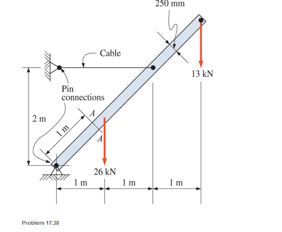
A timber member 150 mm by 250 mm (S4S) is loaded as shown. Calculate the maximum combined stress acting normal to the plane A-A. Neglect the weight of the member.
Expert Solution & Answer
Want to see the full answer?
Check out a sample textbook solution
Students have asked these similar questions
For the ring and the load applied. Calculate the normal stresses at point A and B.
Hint: Normal stresses are due to both the normal force and the bending moment calculated for curved beams.
Given the section is subjected to a moment of 500 N-m, calculate the normal stress in MPa at
the bottom of the section. Use positive for tension and negative for compression.
10 mm
30 mm
10 mm
30 mm
At point A & C, the beam is pin connected. Therefore, find the average normal stress in the 20-mm-diameter cable AB and CD and the average shear stress in the 15-mm-diameter pin at B and D.
Chapter 17 Solutions
Applied Statics and Strength of Materials (6th Edition)
Ch. 17 - Prob. 17.1PCh. 17 - A horizontal 30-ft simple span beam is supported...Ch. 17 - A 1-in.-by-4-in, steel bar is subjected to the...Ch. 17 - A W410100 structural steel wide-flange section is...Ch. 17 - A W1272 structural steel wide-flange section is...Ch. 17 - A solid steel shaft 3 in. in diameter and 4 ft...Ch. 17 - A short compression member is subjected to a...Ch. 17 - With reference to Problem 17.7, calculate the...Ch. 17 - A section of a 51-mm-diameter standard-weight...Ch. 17 - For the pipe of Problem 17.9, compute the maximum...
Ch. 17 - A concrete pedestal is in the shape of a cube and...Ch. 17 - 17.12 For the pedestal of Problem 17.11, assume...Ch. 17 - 17.13 Rework Problem 17.11, but assume that the...Ch. 17 - A 12-in-square concrete pedestal is subjected to a...Ch. 17 - 17.15 A short compression member is subjected to a...Ch. 17 - A rectangular concrete footing, 4 ft by 8 ft in...Ch. 17 - The bending and shear stresses developed at a...Ch. 17 - Stresses developed at a point in a machine part...Ch. 17 - Calculate the principal stresses at points A and B...Ch. 17 - 17.20 Rework Problem 17.19 using P = 8000 lb and...Ch. 17 - 17.21 A 1-in.-square steel bar is subjected to an...Ch. 17 - 17.22 A bar having a cross-sectional area of 6...Ch. 17 - Rework Problem 17.22, changing the load to a...Ch. 17 - Solve Problem l7.17 using Mohr’s circle.Ch. 17 - For the elements shown in Problem 17.18, use...Ch. 17 - Solve Problem 17.19 using Mohr’s circle.Ch. 17 - In Problem 17.19, change the load to 8000 lb and...Ch. 17 - For the following computer problems, any...Ch. 17 - For the following computer problems, any...Ch. 17 - For the following computer problems, any...Ch. 17 - For the following computer problems, any...Ch. 17 - A 4-in.-by-8-in. (S4S) Douglas fir timber beam is...Ch. 17 - A horizontal flexural member (a girt) in the wall...Ch. 17 - A simply supported W1850 structural steel...Ch. 17 - A steel link in a machine is designed to avoid...Ch. 17 - 17.36 An 8-in-square (S4S) vertical timber post is...Ch. 17 - A short 3-in.-square steel bar with a...Ch. 17 - A timber member 150 mm by 250 mm (S4S) is loaded...Ch. 17 - A concrete wall 8 ft high and 3 ft thick is...Ch. 17 - 17.40 A short compression member is subjected to a...Ch. 17 - 17.41 Calculate the maximum eccentric load that...Ch. 17 - A short compression member is subjected to two...Ch. 17 - 17.43 Calculate the force P that may be applied to...Ch. 17 - 17.44 A load of 1000 lb is supported on a...Ch. 17 - 17.45 A short compression member is subjected to...Ch. 17 - 17.46 A structural steel wide-flange section is...Ch. 17 - 17.47 A cast-iron frame for a piece of industrial...Ch. 17 - 17.48 The assembly shown is used in a machine. It...Ch. 17 - 17.49 A 50-mm-diameter solid steel shaft is...Ch. 17 - An element of a machine member is subjected to the...Ch. 17 - 17.51 A short-span cantilever built-up beam has...Ch. 17 - Solve Problem 17.50 using Mohr’s circle.Ch. 17 - 17.53 A cantilever beam is subjected to an...Ch. 17 - A 6-in.-diameter solid shaft is subjected to a...Ch. 17 - Rework parts (b) and (c) of Example 17.7 using...
Knowledge Booster


Learn more about
Need a deep-dive on the concept behind this application? Look no further. Learn more about this topic, mechanical-engineering and related others by exploring similar questions and additional content below.Similar questions
- The uniform 300-1b bar AB carries a 500-lb vertical force at A. The bar is supported by a pin at B and the 0.5-in. diameter cable CD. Find the stress in the cable. DRAW THE FREE BODY DIAGRAM.arrow_forwardThe 7/8-in.-diameter pins at A and C that support the structure are in single shear. Find the largest force F that can be applied to the structure if the working shear stress for these pins is 5000 psi. Neglect the weights of the members. Please only respond to this questions - Solve for F considering member BC. -Evaluate and compare obtained values of F and choose the maximum allowable load for the structure.arrow_forwardA bar having a cross-section areas of 700mm2 is subjected to axial loads at the positions indicated,find the value of stress in the segment QRarrow_forward
- 4. Given the beam loaded as below, label the stress blocks for points A and B. A B A Barrow_forwardWhen sheer force acting on beam at F=60kN,find the sheer stress that occurs on the n-n section and indicate the distribution of the sheer stressarrow_forwardThe composite bar is firmly attached to unyielding supports. Compute the stress in each material caused by the application of the axial load P = 320 kN.arrow_forward
- A cantilever of length 2 metre fails when a load of 2 kN is applied at the freeend. If the section of the beam is 40 mm × 60 mm, find the stress at the failure.arrow_forwardThe compound bar carries the axial forces P and 2P. Find the maximum allowable value of P (in lbs) if the working stresses are 40 ksi for steel and 20 ksi for aluminum, and the total elongation of the bar is not to exceed 0.2arrow_forwardThe pedestal has a triangular cross section as shown, If it is subjected to a compressive force of 500 lb,compute the stress acting on the cross section. 500 lb 12 in. - P(x,y) 3 in. 6 in.arrow_forward
- circular tube AB is fixed at one end andfree at the other end. The tube is subjected to axialforce at joint B. If the outer diameter of the tube is 75 mm and the thickness is 19 mm, calculate the max-imum normal stress in the tube.arrow_forward3-70. A circular rod with a diameter of 40.0 mm has a groove cut to a diameter of 35 mm. A full radius of 3.0mm is produced at the bot- tom of the groove. Compute the maximum stress in the rod when an axial tensile force of 46 kN is applied.arrow_forwardThe uniform 300-lb bar AB carries a 500-lb vertical force at A. The bar is supported by a pin at B and the 0:5-in. diameter cable CD. Find the stress in the cable. 4 ft A 3 ft 3 ft B. 500 Ibarrow_forward
arrow_back_ios
SEE MORE QUESTIONS
arrow_forward_ios
Recommended textbooks for you
 Elements Of ElectromagneticsMechanical EngineeringISBN:9780190698614Author:Sadiku, Matthew N. O.Publisher:Oxford University Press
 Mechanics of Materials (10th Edition)Mechanical EngineeringISBN:9780134319650Author:Russell C. HibbelerPublisher:PEARSON
 Thermodynamics: An Engineering ApproachMechanical EngineeringISBN:9781259822674Author:Yunus A. Cengel Dr., Michael A. BolesPublisher:McGraw-Hill Education
 Control Systems EngineeringMechanical EngineeringISBN:9781118170519Author:Norman S. NisePublisher:WILEY
 Mechanics of Materials (MindTap Course List)Mechanical EngineeringISBN:9781337093347Author:Barry J. Goodno, James M. GerePublisher:Cengage Learning
 Engineering Mechanics: StaticsMechanical EngineeringISBN:9781118807330Author:James L. Meriam, L. G. Kraige, J. N. BoltonPublisher:WILEY
Elements Of Electromagnetics
Mechanical Engineering
ISBN:9780190698614
Author:Sadiku, Matthew N. O.
Publisher:Oxford University Press
Mechanics of Materials (10th Edition)
Mechanical Engineering
ISBN:9780134319650
Author:Russell C. Hibbeler
Publisher:PEARSON
Thermodynamics: An Engineering Approach
Mechanical Engineering
ISBN:9781259822674
Author:Yunus A. Cengel Dr., Michael A. Boles
Publisher:McGraw-Hill Education
Control Systems Engineering
Mechanical Engineering
ISBN:9781118170519
Author:Norman S. Nise
Publisher:WILEY
Mechanics of Materials (MindTap Course List)
Mechanical Engineering
ISBN:9781337093347
Author:Barry J. Goodno, James M. Gere
Publisher:Cengage Learning
Engineering Mechanics: Statics
Mechanical Engineering
ISBN:9781118807330
Author:James L. Meriam, L. G. Kraige, J. N. Bolton
Publisher:WILEY
Differences between Temporary Joining and Permanent Joining.; Author: Academic Gain Tutorials;https://www.youtube.com/watch?v=PTr8QZhgXyg;License: Standard Youtube License