
Applied Statics and Strength of Materials (6th Edition)
6th Edition
ISBN: 9780133840544
Author: George F. Limbrunner, Craig D'Allaird, Leonard Spiegel
Publisher: PEARSON
expand_more
expand_more
format_list_bulleted
Videos
Textbook Question
Chapter 17, Problem 17.9P
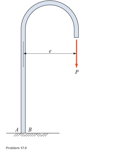
A section of a 51-mm-diameter standard-weight steel pipe is bent into the form shown and rigidly embedded in a concrete footing. Calculate the stresses at points A and B on the pipe. P is 900 N and e is 600 mm.
Expert Solution & Answer
Want to see the full answer?
Check out a sample textbook solution
Students have asked these similar questions
A steel pipe 120 mm external diameter and 60 mm internal diameter is subjected to an internal pressure of 15 N/mm2 and an external pressure of 5 N/mm2. Determine and sketch curves showing the distribution of the radial and circumferential stress across the section using Lame’s equations.
PROBLEM 2. The forces shown in the figure are applied to a plate connected to a pipe with an
outer diameter of 48 mm and an inner diameter of 40 mm. Obtain the stress conditions at the K
and H points and show the stress state on a volume element (cube) taken from each of these
points.
600 N
1000 N
250 mm
AK
100 mm 100 mm
600 N
150 mm
300 N
Find the Normal Stress at points A, B, and C in the Rod below. Dimensions given are diameters.
Chapter 17 Solutions
Applied Statics and Strength of Materials (6th Edition)
Ch. 17 - Prob. 17.1PCh. 17 - A horizontal 30-ft simple span beam is supported...Ch. 17 - A 1-in.-by-4-in, steel bar is subjected to the...Ch. 17 - A W410100 structural steel wide-flange section is...Ch. 17 - A W1272 structural steel wide-flange section is...Ch. 17 - A solid steel shaft 3 in. in diameter and 4 ft...Ch. 17 - A short compression member is subjected to a...Ch. 17 - With reference to Problem 17.7, calculate the...Ch. 17 - A section of a 51-mm-diameter standard-weight...Ch. 17 - For the pipe of Problem 17.9, compute the maximum...
Ch. 17 - A concrete pedestal is in the shape of a cube and...Ch. 17 - 17.12 For the pedestal of Problem 17.11, assume...Ch. 17 - 17.13 Rework Problem 17.11, but assume that the...Ch. 17 - A 12-in-square concrete pedestal is subjected to a...Ch. 17 - 17.15 A short compression member is subjected to a...Ch. 17 - A rectangular concrete footing, 4 ft by 8 ft in...Ch. 17 - The bending and shear stresses developed at a...Ch. 17 - Stresses developed at a point in a machine part...Ch. 17 - Calculate the principal stresses at points A and B...Ch. 17 - 17.20 Rework Problem 17.19 using P = 8000 lb and...Ch. 17 - 17.21 A 1-in.-square steel bar is subjected to an...Ch. 17 - 17.22 A bar having a cross-sectional area of 6...Ch. 17 - Rework Problem 17.22, changing the load to a...Ch. 17 - Solve Problem l7.17 using Mohr’s circle.Ch. 17 - For the elements shown in Problem 17.18, use...Ch. 17 - Solve Problem 17.19 using Mohr’s circle.Ch. 17 - In Problem 17.19, change the load to 8000 lb and...Ch. 17 - For the following computer problems, any...Ch. 17 - For the following computer problems, any...Ch. 17 - For the following computer problems, any...Ch. 17 - For the following computer problems, any...Ch. 17 - A 4-in.-by-8-in. (S4S) Douglas fir timber beam is...Ch. 17 - A horizontal flexural member (a girt) in the wall...Ch. 17 - A simply supported W1850 structural steel...Ch. 17 - A steel link in a machine is designed to avoid...Ch. 17 - 17.36 An 8-in-square (S4S) vertical timber post is...Ch. 17 - A short 3-in.-square steel bar with a...Ch. 17 - A timber member 150 mm by 250 mm (S4S) is loaded...Ch. 17 - A concrete wall 8 ft high and 3 ft thick is...Ch. 17 - 17.40 A short compression member is subjected to a...Ch. 17 - 17.41 Calculate the maximum eccentric load that...Ch. 17 - A short compression member is subjected to two...Ch. 17 - 17.43 Calculate the force P that may be applied to...Ch. 17 - 17.44 A load of 1000 lb is supported on a...Ch. 17 - 17.45 A short compression member is subjected to...Ch. 17 - 17.46 A structural steel wide-flange section is...Ch. 17 - 17.47 A cast-iron frame for a piece of industrial...Ch. 17 - 17.48 The assembly shown is used in a machine. It...Ch. 17 - 17.49 A 50-mm-diameter solid steel shaft is...Ch. 17 - An element of a machine member is subjected to the...Ch. 17 - 17.51 A short-span cantilever built-up beam has...Ch. 17 - Solve Problem 17.50 using Mohr’s circle.Ch. 17 - 17.53 A cantilever beam is subjected to an...Ch. 17 - A 6-in.-diameter solid shaft is subjected to a...Ch. 17 - Rework parts (b) and (c) of Example 17.7 using...
Knowledge Booster


Learn more about
Need a deep-dive on the concept behind this application? Look no further. Learn more about this topic, mechanical-engineering and related others by exploring similar questions and additional content below.Similar questions
- Eight steel cables (with equal distance to each other) are supporting a circular heavy moulding of diameter 3m from an overhead point. If the moulding weighs 5 kN/m and the attachment point is 4m above it, determine the following:a. Calculate the tension of the cable.b. Determine the diameter of the wire if the allowable stress is 125 MPa.c. If the diameter of the cable is 10 mm, find the deflection of the steel cable.d. If the diameter of the cable is 10 mm, find the vertical displacement of the molder.arrow_forwardA simply supported wood beam is subjected to uniformly distributed load q. The width of the beam is 6 in, and the height is 8 in. Determine the normal stress and the shear stress at point C. Show these stresses on a sketch of a stress element at point C.arrow_forwardTwo solid cylindrical rods (1) and (2) are joined together at flange B and loaded, as shown. The diameter of rod (1) is d1 = 1.66 in. and the diameter of rod (2) is d2 = 2.68 in. Determine the normal stresses in rods (1) and (2). Assume P = 17 kips and Q = 29 kips. Use positive for tensile stress and negative for compressive stress.arrow_forward
- A simplified model of a basketball hoop is shown. During a basket dunk a player hangs from the rim applying a force of 320 lbs including a dynamic load factor. The stand is a square tube with 5 inches outside length and 0.25 inches thickness. The distance from the edge of the rim to the middle of the square tube is 4 ft. Assuming the model is rigid, the normal stress at point A is most closely equal to: a. 1284 psi b. 1248 psi c. 1212 psi d. 36 psi Aarrow_forwardA bar of rectangular section shown in is subjected to stresses σx, σy and σz in x, y and z directions respectively. Show that if sum of these stresses is zero, there is no change in volume of the bar.arrow_forwardA solid steel bar with a diameter of 50 mm is subjected to three forces as shown in the figure, determine the main stresses in point B.arrow_forward
- A steel rod 20 mm in diameter passes centrally through a steel tube of 25 mm internal diameter and 30 mm external diameter. The tube is 800 mm long and is closed by rigid washers of negligible thickness which are fastened by nuts threaded on the rod. The nuts are tightened until the compressive load on the tube is 20 kN. Calculate the stresses in the tube and the rod.Find the increase in these stresses when one nut is tightened by one-quarter of a turn relative to the other. There are 4 threads per 10 mm. Take E = 2 x 10⁵ N/mm2.arrow_forwardA rigid plate (AC) is connected to flat steel bars by pins at A and B. The horizontal flat steel bar ED is also connected via pins at points E and D. Member AE consists of two 6 mm by 25 mm parallel flat bars, while members EB and ED are single flat bars with dimensions 8 mm by 30 mm. If the structure is subjected to a 2-kip vertical force at point A, find the axial (normal) stress in members AE, EB, and ED. A 2 kip -3'- E B D -3'- C 4'arrow_forwardThe compound bar carries the axial forces P and 2P. Find the maximum allowable value of P (in lbs) if the working stresses are 40 ksi for steel and 20 ksi for aluminum, and the total elongation of the bar is not to exceed 0.2arrow_forward
- A pipe carrying steam at 3.5 MPa has an outside diameter of 450 mm and a wall thickness of 10 mm. A gasket is inserted between the flange at one end of the pipe and a flat plate used to cap the end. How many 40-mm-diameter bolts must be used to hold the cap on if the allowable stress in the bolts is 105 MPa, of which 55 MPa is the initial stress? What circumferential stress is developed in the pipe? Why is it necessary to tighten the bolt initially, and what will happen if the steam pressure should cause the stress in the bolts to be twice the value of the initial stress? *arrow_forwardcircular tube AB is fixed at one end andfree at the other end. The tube is subjected to axialforce at joint B. If the outer diameter of the tube is 75 mm and the thickness is 19 mm, calculate the max-imum normal stress in the tube.arrow_forward1. Two cables A and B had their both ends attached to each other as shown. Cable A is 10 in long and cable B is 0.5 in longer than cable A; hence making cable B slack. The diameter of cable A is 0.70 in. while cable B has a diameter of 0.25 in. Find the stresses for both cables if the system supports a downward force P = 0.15kip. Use E = 50ksi. Parrow_forward
arrow_back_ios
SEE MORE QUESTIONS
arrow_forward_ios
Recommended textbooks for you
 Elements Of ElectromagneticsMechanical EngineeringISBN:9780190698614Author:Sadiku, Matthew N. O.Publisher:Oxford University Press
 Mechanics of Materials (10th Edition)Mechanical EngineeringISBN:9780134319650Author:Russell C. HibbelerPublisher:PEARSON
 Thermodynamics: An Engineering ApproachMechanical EngineeringISBN:9781259822674Author:Yunus A. Cengel Dr., Michael A. BolesPublisher:McGraw-Hill Education
 Control Systems EngineeringMechanical EngineeringISBN:9781118170519Author:Norman S. NisePublisher:WILEY
 Mechanics of Materials (MindTap Course List)Mechanical EngineeringISBN:9781337093347Author:Barry J. Goodno, James M. GerePublisher:Cengage Learning
 Engineering Mechanics: StaticsMechanical EngineeringISBN:9781118807330Author:James L. Meriam, L. G. Kraige, J. N. BoltonPublisher:WILEY
Elements Of Electromagnetics
Mechanical Engineering
ISBN:9780190698614
Author:Sadiku, Matthew N. O.
Publisher:Oxford University Press
Mechanics of Materials (10th Edition)
Mechanical Engineering
ISBN:9780134319650
Author:Russell C. Hibbeler
Publisher:PEARSON
Thermodynamics: An Engineering Approach
Mechanical Engineering
ISBN:9781259822674
Author:Yunus A. Cengel Dr., Michael A. Boles
Publisher:McGraw-Hill Education
Control Systems Engineering
Mechanical Engineering
ISBN:9781118170519
Author:Norman S. Nise
Publisher:WILEY
Mechanics of Materials (MindTap Course List)
Mechanical Engineering
ISBN:9781337093347
Author:Barry J. Goodno, James M. Gere
Publisher:Cengage Learning
Engineering Mechanics: Statics
Mechanical Engineering
ISBN:9781118807330
Author:James L. Meriam, L. G. Kraige, J. N. Bolton
Publisher:WILEY
Differences between Temporary Joining and Permanent Joining.; Author: Academic Gain Tutorials;https://www.youtube.com/watch?v=PTr8QZhgXyg;License: Standard Youtube License