
Loose Leaf for Engineering Circuit Analysis Format: Loose-leaf
9th Edition
ISBN: 9781259989452
Author: Hayt
Publisher: Mcgraw Hill Publishers
expand_more
expand_more
format_list_bulleted
Videos
Textbook Question
Chapter 11, Problem 15E
Find the average power for each element in the circuit of Fig. 11.32.
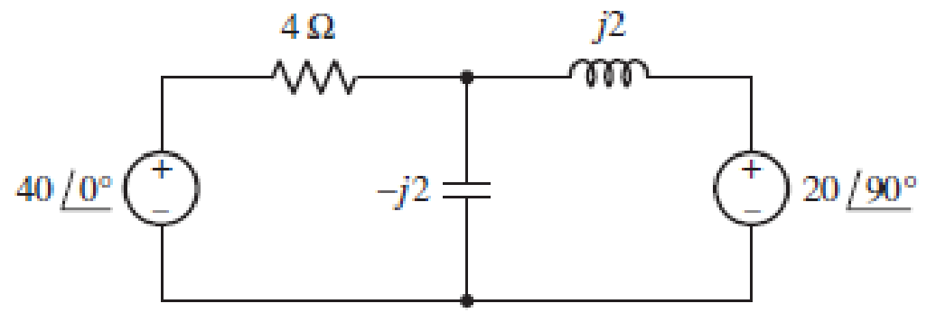
■ FIGURE 11.32
Expert Solution & Answer
Want to see the full answer?
Check out a sample textbook solution
Students have asked these similar questions
For a certain alternating current, i(t), [A] i = 2 ⋅ sin (500 π ⋅ t + ) π, where the time is in seconds. a) Enter the peak value of the current b) Enter the rms value of the current c) Determine the period time d) Enter the frequency of the alternating current
11.33 For the following voltage and current phasors,
calculate the complex power, apparent power, real
power, and reactive power. Specify whether the pf is
leading or lagging.
(a) V = 220/30° V mms, I = 0.5/60° A rms
(b) V=250/-10° V rms,
1= 6.2/-25° Arms
(c) V = 120/0° V rms, I = 2.4/-15° Arms
(d) V = 160/45° V rms, I = 8.5/90° Arms
Example 11.8. An alternating current is given by;
i = 10 sin 942 t
Determine the time taken from t = 0 for the current to reach a value of + 6 A for a first and
second time.
Chapter 11 Solutions
Loose Leaf for Engineering Circuit Analysis Format: Loose-leaf
Ch. 11.1 - A current source of 12 cos 2000t A, a 200 ....Ch. 11.2 - Given the phasor voltage across an impedance ,...Ch. 11.2 - Prob. 3PCh. 11.2 - Prob. 4PCh. 11.2 - A voltage source vs is connected across a 4...Ch. 11.3 - If the 30 mH inductor of Example 11.7 is replaced...Ch. 11.4 - Calculate the effective value of each of the...Ch. 11.5 - For the circuit of Fig. 11.16, determine the power...Ch. 11.6 - Prob. 10PCh. 11 - Prob. 1E
Ch. 11 - Determine the power absorbed at t = 1.5 ms by each...Ch. 11 - Calculate the power absorbed at t = 0, t = 0+, and...Ch. 11 - Three elements are connected in parallel: a 1 k...Ch. 11 - Let is = 4u(t) A in the circuit of Fig. 11.28. (a)...Ch. 11 - Prob. 6ECh. 11 - Assuming no transients are present, calculate the...Ch. 11 - Prob. 8ECh. 11 - Prob. 9ECh. 11 - Prob. 10ECh. 11 - The phasor current I=915mA (corresponding to a...Ch. 11 - A phasor voltage V=10045V (the sinusoid operates...Ch. 11 - Prob. 13ECh. 11 - Prob. 14ECh. 11 - Find the average power for each element in the...Ch. 11 - (a) Calculate the average power absorbed by each...Ch. 11 - Prob. 17ECh. 11 - Prob. 18ECh. 11 - Prob. 19ECh. 11 - The circuit in Fig. 11.36 has a series resistance...Ch. 11 - Prob. 21ECh. 11 - Prob. 22ECh. 11 - Prob. 23ECh. 11 - Prob. 24ECh. 11 - Prob. 25ECh. 11 - Prob. 26ECh. 11 - Prob. 27ECh. 11 - Prob. 28ECh. 11 - Prob. 29ECh. 11 - Prob. 30ECh. 11 - Prob. 31ECh. 11 - Prob. 32ECh. 11 - Prob. 33ECh. 11 - (a) Calculate both the average and rms values of...Ch. 11 - Prob. 35ECh. 11 - FIGURE 11.43 Calculate the power factor of the...Ch. 11 - Prob. 37ECh. 11 - Prob. 38ECh. 11 - Prob. 40ECh. 11 - Prob. 41ECh. 11 - Prob. 42ECh. 11 - Prob. 43ECh. 11 - Compute the complex power S (in polar form) drawn...Ch. 11 - Calculate the apparent power, power factor, and...Ch. 11 - Prob. 46ECh. 11 - Prob. 48ECh. 11 - Prob. 49ECh. 11 - Prob. 50ECh. 11 - Prob. 51ECh. 11 - Prob. 52ECh. 11 - FIGURE 11.49 Instead of including a capacitor as...Ch. 11 - Prob. 54ECh. 11 - A load is drawing 10 A rms when connected to a...Ch. 11 - For the circuit of Fig. 11.50, assume the source...Ch. 11 - Prob. 57ECh. 11 - A source 45 sin 32t V is connected in series with...Ch. 11 - Prob. 60ECh. 11 - FIGURE 11.51 The circuit in Fig. 11.51 uses a Pi...Ch. 11 - Prob. 62ECh. 11 - Prob. 63ECh. 11 - You would like to maximize power transfer to a 50 ...
Knowledge Booster


Learn more about
Need a deep-dive on the concept behind this application? Look no further. Learn more about this topic, electrical-engineering and related others by exploring similar questions and additional content below.Similar questions
- PRACTICE PROBLEM II.10 Calculate the power factor of the entire circuit of Fig. 11.19 as seen by the source. What is the average power supplied by the source? Answer: 0.936 lagging, 118 W. 40/0°V rms Figure 11.19 10 92 892 www www ell j4Q2 For Practice Prob. 11.10. -j6 Qarrow_forwardFor the circuit in fig .11.82 A. Write the mathematical expressions for the current IL and the voltage Vl following the closing of the switch. B. Sketch the waveform of iL and VL for the entire period from initial value to steady-state level.arrow_forward2. A resistor of 6Q and an unknown impedance coil in series draw 12 amps from a 120 volts, 60 Hz line. If the real power taken from the line is 1,152 watts, what is the coil inductance? Two spheres senarated from each other by 10 m have a chared of 0 001 Coulomh and 0 003arrow_forward
- 11.19 The variable resistor R in the circuit of Fig. 11.50 is adjusted until it absorbs the maximum average power. Find R and the maximum average power absorbed. j1Ω 3 Figure 11.50 For Prob. 11.19. 392 www 4/0° A wwww -j2Q2 692 Rarrow_forwardSection 11.8 Power Factor Correction 11.69 Refer to the circuit shown in Fig. 11.88. (a) What is the power factor? (b) What is the average power dissipated? (c) What is the value of the capacitance that will give a unity power factor when connected to the load? 120 V rms Z 10 +j122 60 Hzarrow_forwardReferring to the Figure 2, compute the following values, given that the operating frequency is 60Hz and the voltage is 120V: (a) The inductive reactance (b) Source current (c) Apparent power, active power and reactive power Sketch and illustrate the power triangle with proper labelling, units and values. E 160 150 mH Figure 2arrow_forward
- 11.75 Consider the power system shown in Fig. 11.90. Calculate: (a) the total complex power (b) the power factor (c) the parallel capacitance necessary to establish a unity power factor O- + 240 V rms, 50 Hz - Figure 11.90 For Prob. 11.75. 80-j50 92 120 + j70 Ω 60+j0 22arrow_forwardCalculate the power factor of the entire circuit of Fig. 11.19 as seen by Practice Problem 11.10 the source. What is the average power supplied by the source? 10 2 82 Ar 165/0° V rms j42 Figure 11.19 For Practice Prob. 11.10.arrow_forwardA capacitor drawing 4 kvar is placed in parallel with the electro-magnet that draws 3 kW of active power and 4 kvar of reactive power.. a. Calculate the new value of apparent power b. What is the new value of reactive power? c. What is the value of active power? d. What is the new power factor?arrow_forward
- 11.24 Determine the rms value of the waveform in Fig. 11.55. v(t) A 5 0 -5 Figure 11.55 For Prob. 11.24. 1 2 3 4 tarrow_forwardPRACTICE PROBLEM II.10 Calculate the power factor of the entire circuit of Fig. 11.19 as seen by the source. What is the average power supplied by the source? Answer: 0.936 lagging, 118 W. 40/0° V rms Figure 11.19 10 22 ww 892 www j4 92 For Practice Prob. 11.10. -j6 92arrow_forwardPRACTICE PROBLEM 11.6 In Fig. 11.12, the resistor R₁ is adjusted until it absorbs the maximum average power. Calculate R₁ and the maximum average power absorbed by it. 120/60° V Figure 11.12 80 92 www j60 92 m Answer: 30 S2, 9.883 W. 90 92 For Practice Prob. 11.6. -j30 92 RLarrow_forward
arrow_back_ios
SEE MORE QUESTIONS
arrow_forward_ios
Recommended textbooks for you
 Introductory Circuit Analysis (13th Edition)Electrical EngineeringISBN:9780133923605Author:Robert L. BoylestadPublisher:PEARSON
 Delmar's Standard Textbook Of ElectricityElectrical EngineeringISBN:9781337900348Author:Stephen L. HermanPublisher:Cengage Learning
 Programmable Logic ControllersElectrical EngineeringISBN:9780073373843Author:Frank D. PetruzellaPublisher:McGraw-Hill Education
 Fundamentals of Electric CircuitsElectrical EngineeringISBN:9780078028229Author:Charles K Alexander, Matthew SadikuPublisher:McGraw-Hill Education
 Electric Circuits. (11th Edition)Electrical EngineeringISBN:9780134746968Author:James W. Nilsson, Susan RiedelPublisher:PEARSON
 Engineering ElectromagneticsElectrical EngineeringISBN:9780078028151Author:Hayt, William H. (william Hart), Jr, BUCK, John A.Publisher:Mcgraw-hill Education,
Introductory Circuit Analysis (13th Edition)
Electrical Engineering
ISBN:9780133923605
Author:Robert L. Boylestad
Publisher:PEARSON
Delmar's Standard Textbook Of Electricity
Electrical Engineering
ISBN:9781337900348
Author:Stephen L. Herman
Publisher:Cengage Learning
Programmable Logic Controllers
Electrical Engineering
ISBN:9780073373843
Author:Frank D. Petruzella
Publisher:McGraw-Hill Education
Fundamentals of Electric Circuits
Electrical Engineering
ISBN:9780078028229
Author:Charles K Alexander, Matthew Sadiku
Publisher:McGraw-Hill Education
Electric Circuits. (11th Edition)
Electrical Engineering
ISBN:9780134746968
Author:James W. Nilsson, Susan Riedel
Publisher:PEARSON
Engineering Electromagnetics
Electrical Engineering
ISBN:9780078028151
Author:Hayt, William H. (william Hart), Jr, BUCK, John A.
Publisher:Mcgraw-hill Education,
02 - Sinusoidal AC Voltage Sources in Circuits, Part 1; Author: Math and Science;https://www.youtube.com/watch?v=8zMiIHVMfaw;License: Standard Youtube License