
Loose Leaf for Engineering Circuit Analysis Format: Loose-leaf
9th Edition
ISBN: 9781259989452
Author: Hayt
Publisher: Mcgraw Hill Publishers
expand_more
expand_more
format_list_bulleted
Videos
Textbook Question
Chapter 11, Problem 2E
Determine the power absorbed at t = 1.5 ms by each of the three elements of the circuit shown in Fig. 11.26 if vs is equal to (a) 30u(−t) V; (b) 10 + 20u(t) V.
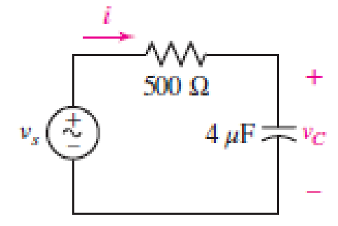
■ FIGURE 11.26
Expert Solution & Answer
Want to see the full answer?
Check out a sample textbook solution
Students have asked these similar questions
Example 11.8. An alternating current is given by;
i = 10 sin 942 t
Determine the time taken from t = 0 for the current to reach a value of + 6 A for a first and
second time.
(a) Considering pure inductance in an ac circuit element, show that the alternating current lags the voltage by ᴨ/2.
(b) Derive the Norton equivalent network with respect to terminals PQ for the network shown in Figure below and hence determine the magnitude of the current flowing in a 2Ὡ resistor connected across PQ
Given a series circuit comprised of the following element: 81.59-ohm resistor, practical inductor with internal resistance of 0.99 ohm and reactance of 54.29 ohms; and a capacitor with reactance of 6.15 ohms. Compute for equivalent impedance angle in degrees.
Note: Follow this reminder carefully. Compute to the nearest 4 decimal places. No Scientific notation. Do not round off in the middle of calculation. Use stored values. Write the numerical values only. No units in your final answer. Spaces are not allowed. Excessive number of decimals as compared to the required number of decimals may result to an incorrect answer.
Chapter 11 Solutions
Loose Leaf for Engineering Circuit Analysis Format: Loose-leaf
Ch. 11.1 - A current source of 12 cos 2000t A, a 200 ....Ch. 11.2 - Given the phasor voltage across an impedance ,...Ch. 11.2 - Prob. 3PCh. 11.2 - Prob. 4PCh. 11.2 - A voltage source vs is connected across a 4...Ch. 11.3 - If the 30 mH inductor of Example 11.7 is replaced...Ch. 11.4 - Calculate the effective value of each of the...Ch. 11.5 - For the circuit of Fig. 11.16, determine the power...Ch. 11.6 - Prob. 10PCh. 11 - Prob. 1E
Ch. 11 - Determine the power absorbed at t = 1.5 ms by each...Ch. 11 - Calculate the power absorbed at t = 0, t = 0+, and...Ch. 11 - Three elements are connected in parallel: a 1 k...Ch. 11 - Let is = 4u(t) A in the circuit of Fig. 11.28. (a)...Ch. 11 - Prob. 6ECh. 11 - Assuming no transients are present, calculate the...Ch. 11 - Prob. 8ECh. 11 - Prob. 9ECh. 11 - Prob. 10ECh. 11 - The phasor current I=915mA (corresponding to a...Ch. 11 - A phasor voltage V=10045V (the sinusoid operates...Ch. 11 - Prob. 13ECh. 11 - Prob. 14ECh. 11 - Find the average power for each element in the...Ch. 11 - (a) Calculate the average power absorbed by each...Ch. 11 - Prob. 17ECh. 11 - Prob. 18ECh. 11 - Prob. 19ECh. 11 - The circuit in Fig. 11.36 has a series resistance...Ch. 11 - Prob. 21ECh. 11 - Prob. 22ECh. 11 - Prob. 23ECh. 11 - Prob. 24ECh. 11 - Prob. 25ECh. 11 - Prob. 26ECh. 11 - Prob. 27ECh. 11 - Prob. 28ECh. 11 - Prob. 29ECh. 11 - Prob. 30ECh. 11 - Prob. 31ECh. 11 - Prob. 32ECh. 11 - Prob. 33ECh. 11 - (a) Calculate both the average and rms values of...Ch. 11 - Prob. 35ECh. 11 - FIGURE 11.43 Calculate the power factor of the...Ch. 11 - Prob. 37ECh. 11 - Prob. 38ECh. 11 - Prob. 40ECh. 11 - Prob. 41ECh. 11 - Prob. 42ECh. 11 - Prob. 43ECh. 11 - Compute the complex power S (in polar form) drawn...Ch. 11 - Calculate the apparent power, power factor, and...Ch. 11 - Prob. 46ECh. 11 - Prob. 48ECh. 11 - Prob. 49ECh. 11 - Prob. 50ECh. 11 - Prob. 51ECh. 11 - Prob. 52ECh. 11 - FIGURE 11.49 Instead of including a capacitor as...Ch. 11 - Prob. 54ECh. 11 - A load is drawing 10 A rms when connected to a...Ch. 11 - For the circuit of Fig. 11.50, assume the source...Ch. 11 - Prob. 57ECh. 11 - A source 45 sin 32t V is connected in series with...Ch. 11 - Prob. 60ECh. 11 - FIGURE 11.51 The circuit in Fig. 11.51 uses a Pi...Ch. 11 - Prob. 62ECh. 11 - Prob. 63ECh. 11 - You would like to maximize power transfer to a 50 ...
Knowledge Booster


Learn more about
Need a deep-dive on the concept behind this application? Look no further. Learn more about this topic, electrical-engineering and related others by exploring similar questions and additional content below.Similar questions
- O Screenshot Y... -> T.I1.6 For the circuit shown in fig. 11.10, the expression for current through inductor L. Fig. 11.10 is given by i, (1) =(10+30r)e for 12 0 Find, (a) the values of L,C (b) initial condition v (0) (c) the expression for v,(1) >0. wwarrow_forward7. For the circuit shown below: a) Calculate the real and reactive power associated with each circuit element. b) Is the average power generated equals the average power absorbed? c) Is the magnetizing vars generated equal the magnetizing vars absorbed? Is-10 5 Ω Vo≤80 15/0° A 2.51arrow_forwardGiven a series circuit comprised of the following element: 77.03-ohm resistor, practical inductor with internal resistance of 0.16 ohm and reactance of 74.36 ohms; and a capacitor with reactance of 12.45 ohms. Compute for the magnitude of its equivalent impedance in ohms. Note: Follow this reminder carefully. Compute to the nearest 4 decimal places. No Scientific notation. Do not round off in the middle of calculation. Use stored values.arrow_forward
- When a car has a dead battery, it can often be started by connecting the battery from another car across its terminals. The positive terminals are connected together as are the negative terminals. The connections in the circuit are shown in Figure. The current i is 30 A. Which car has the dead battery в 12V 12V O A O B O Both of them O Null 11:10 AM P Type here to search 耳。 a 40) ENG 4/8/2021 67 7 8 A9 Aarrow_forward11:23 ::! The figure shows the current through and the voltage across adevice. a) sketch the power delivered to the device for t>0. b) Find the total Energy absorbed by the device for the periodof 0arrow_forwardRioad load BjoLoad Road (50 points) 网Load load source load source An electric dryer with an equivalent series resistance and inductance of values 9 N and 26 mH is plugged into a standard 240V(RMS) 60HZ wall socket. You may assume the phase of the source voltage is zero. a) Calculate the load current. 7. A help (numbers) I load !! In the time domain, A help (formulas) i toad (t) =arrow_forwardA natural waterfalls, 50 meters high, constantly discharges 1.3m3 per second. A minihydroelectric plant is to be constructed at the bottom of the waterfalls. Calculate theelectric generator kW rating, assuming 90% mechanical to electrical conversion efficiencyand water turbine design efficiency of 70%.arrow_forwardConsider an RC series circuit with supplied voltage, Vs = 1 Vpeak (Figure C) If R = 10 K ohm, C = 1 mirco Farad, then what is the value of Time Constant, T? b. How long а. will it take the capacitor to get fully charged and discharged? c. List the equipments' name to construct and to analyze the RC series circuit? 10.0k2 С1 V1 1uF 1V 1kHz 0° Figure: Carrow_forwardDetermine each system if Static or Dynamic (5 points), Linear or Non-Linear (5 points), Time Variant or Time Invariant (5 points), Causal or Non Causal (5 points). Show proof for each answer. 1. Y1(n)=x(n)sin(2*pi*n) Please answer this immediately. Thank you!arrow_forwardDo we require three sets of individual 1 Ø Alternators in order to build a 3 Ø Alternator that is capable of producing 3 Ø electrical power output? Give a succinct explanation of your response using only one (1) sentence.arrow_forwardElectrical Engineering CSE-310, Spring 2021 Quiz-2, Date: April 26, 2021 Q.1: Calculate the output voltage of the following circuit 100 k2 20 ka V,-1.5 V V.arrow_forwardA resistor of 50 ohms, a 200mH inductor, and a 1.5 x 10⁻⁴ F capacitor are connected in parallel to a 120-volt, 60 cps source. Calculate: a) the total real, reactive, and apparent powers; b) power factor.arrow_forwardarrow_back_iosSEE MORE QUESTIONSarrow_forward_ios
Recommended textbooks for you
 Introductory Circuit Analysis (13th Edition)Electrical EngineeringISBN:9780133923605Author:Robert L. BoylestadPublisher:PEARSON
 Delmar's Standard Textbook Of ElectricityElectrical EngineeringISBN:9781337900348Author:Stephen L. HermanPublisher:Cengage Learning
 Programmable Logic ControllersElectrical EngineeringISBN:9780073373843Author:Frank D. PetruzellaPublisher:McGraw-Hill Education
 Fundamentals of Electric CircuitsElectrical EngineeringISBN:9780078028229Author:Charles K Alexander, Matthew SadikuPublisher:McGraw-Hill Education
 Electric Circuits. (11th Edition)Electrical EngineeringISBN:9780134746968Author:James W. Nilsson, Susan RiedelPublisher:PEARSON
 Engineering ElectromagneticsElectrical EngineeringISBN:9780078028151Author:Hayt, William H. (william Hart), Jr, BUCK, John A.Publisher:Mcgraw-hill Education,
Introductory Circuit Analysis (13th Edition)
Electrical Engineering
ISBN:9780133923605
Author:Robert L. Boylestad
Publisher:PEARSON
Delmar's Standard Textbook Of Electricity
Electrical Engineering
ISBN:9781337900348
Author:Stephen L. Herman
Publisher:Cengage Learning
Programmable Logic Controllers
Electrical Engineering
ISBN:9780073373843
Author:Frank D. Petruzella
Publisher:McGraw-Hill Education
Fundamentals of Electric Circuits
Electrical Engineering
ISBN:9780078028229
Author:Charles K Alexander, Matthew Sadiku
Publisher:McGraw-Hill Education
Electric Circuits. (11th Edition)
Electrical Engineering
ISBN:9780134746968
Author:James W. Nilsson, Susan Riedel
Publisher:PEARSON
Engineering Electromagnetics
Electrical Engineering
ISBN:9780078028151
Author:Hayt, William H. (william Hart), Jr, BUCK, John A.
Publisher:Mcgraw-hill Education,
02 - Sinusoidal AC Voltage Sources in Circuits, Part 1; Author: Math and Science;https://www.youtube.com/watch?v=8zMiIHVMfaw;License: Standard Youtube License