
Loose Leaf for Engineering Circuit Analysis Format: Loose-leaf
9th Edition
ISBN: 9781259989452
Author: Hayt
Publisher: Mcgraw Hill Publishers
expand_more
expand_more
format_list_bulleted
Concept explainers
Videos
Textbook Question
thumb_up100%
Chapter 11, Problem 36E
FIGURE 11.43
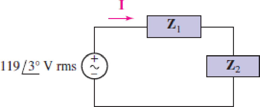
Calculate the power factor of the combined loads of the circuit depicted in Fig. 11.43 if (a) both loads are purely resistive; (b) both loads are purely inductive and ω = 100 rad/s; (c) both loads are purely capacitive and ω = 200 rad/s; (d) Z1 = 2Z2 = 5 − j8 Ω.
Expert Solution & Answer
Want to see the full answer?
Check out a sample textbook solution
Students have asked these similar questions
Understand ac power concepts, their relationships to one another, and how to calculate them in a circuitA load consisting of a 1.35 kΩ resistor in parallel with a 405 mH inductor is connected across the terminals of a sinusoidal voltage source vg, where vg = 90 cos 2500t V. Find
1. a) the average power delivered to the load,2. b) the reactive power for the load,3. c) the apparent power for the load, and4. d) the power factor of the load.
For the circuit shown in Fig Q2, determine:
(a) The total impedance seen by the source.
(b) The total supply current (1)
(c) The voltage across the capacitors (Ve)
(d) The active power, reactive power and
power factor of the source.
R₁5602
E = 100V 200
560
+
fr
= 400
R₂200
+
Ve
Fig. Q2
Xc₁ = 400
An impedance ZL = (11.5 + j10) ohms is connected in parallel with an impedance ZC = (8 – j20)ohms. Calculate: a) the conductance, susceptance, and admittance of each branch; b) the totalconductance, susceptance, and admittance; c) the total current in polar form if the sourcevoltage is used as the reference; d) the total real, reactive, and apparent powers; e) the overallpower factor.
Chapter 11 Solutions
Loose Leaf for Engineering Circuit Analysis Format: Loose-leaf
Ch. 11.1 - A current source of 12 cos 2000t A, a 200 ....Ch. 11.2 - Given the phasor voltage across an impedance ,...Ch. 11.2 - Prob. 3PCh. 11.2 - Prob. 4PCh. 11.2 - A voltage source vs is connected across a 4...Ch. 11.3 - If the 30 mH inductor of Example 11.7 is replaced...Ch. 11.4 - Calculate the effective value of each of the...Ch. 11.5 - For the circuit of Fig. 11.16, determine the power...Ch. 11.6 - Prob. 10PCh. 11 - Prob. 1E
Ch. 11 - Determine the power absorbed at t = 1.5 ms by each...Ch. 11 - Calculate the power absorbed at t = 0, t = 0+, and...Ch. 11 - Three elements are connected in parallel: a 1 k...Ch. 11 - Let is = 4u(t) A in the circuit of Fig. 11.28. (a)...Ch. 11 - Prob. 6ECh. 11 - Assuming no transients are present, calculate the...Ch. 11 - Prob. 8ECh. 11 - Prob. 9ECh. 11 - Prob. 10ECh. 11 - The phasor current I=915mA (corresponding to a...Ch. 11 - A phasor voltage V=10045V (the sinusoid operates...Ch. 11 - Prob. 13ECh. 11 - Prob. 14ECh. 11 - Find the average power for each element in the...Ch. 11 - (a) Calculate the average power absorbed by each...Ch. 11 - Prob. 17ECh. 11 - Prob. 18ECh. 11 - Prob. 19ECh. 11 - The circuit in Fig. 11.36 has a series resistance...Ch. 11 - Prob. 21ECh. 11 - Prob. 22ECh. 11 - Prob. 23ECh. 11 - Prob. 24ECh. 11 - Prob. 25ECh. 11 - Prob. 26ECh. 11 - Prob. 27ECh. 11 - Prob. 28ECh. 11 - Prob. 29ECh. 11 - Prob. 30ECh. 11 - Prob. 31ECh. 11 - Prob. 32ECh. 11 - Prob. 33ECh. 11 - (a) Calculate both the average and rms values of...Ch. 11 - Prob. 35ECh. 11 - FIGURE 11.43 Calculate the power factor of the...Ch. 11 - Prob. 37ECh. 11 - Prob. 38ECh. 11 - Prob. 40ECh. 11 - Prob. 41ECh. 11 - Prob. 42ECh. 11 - Prob. 43ECh. 11 - Compute the complex power S (in polar form) drawn...Ch. 11 - Calculate the apparent power, power factor, and...Ch. 11 - Prob. 46ECh. 11 - Prob. 48ECh. 11 - Prob. 49ECh. 11 - Prob. 50ECh. 11 - Prob. 51ECh. 11 - Prob. 52ECh. 11 - FIGURE 11.49 Instead of including a capacitor as...Ch. 11 - Prob. 54ECh. 11 - A load is drawing 10 A rms when connected to a...Ch. 11 - For the circuit of Fig. 11.50, assume the source...Ch. 11 - Prob. 57ECh. 11 - A source 45 sin 32t V is connected in series with...Ch. 11 - Prob. 60ECh. 11 - FIGURE 11.51 The circuit in Fig. 11.51 uses a Pi...Ch. 11 - Prob. 62ECh. 11 - Prob. 63ECh. 11 - You would like to maximize power transfer to a 50 ...
Knowledge Booster


Learn more about
Need a deep-dive on the concept behind this application? Look no further. Learn more about this topic, electrical-engineering and related others by exploring similar questions and additional content below.Similar questions
- Circuit Diagram Computed Values Compute the expected power factor of the circuit given the different capacitance. R1 V1 500 220Vrms C1 60Hz oº 100μl L (RMS) Capacitance Real Power (UE) (Watts) mag (A) 40 ~ 30 20 2 11 100mH Reactive Power (Vars) Power Factorarrow_forwardCircuit Diagram Computed Values Compute the expected power factor of the circuit given the different capacitance. R1 V1 5002 220V (1 60Hz 0° 100μl It (RMS) Capacitance Real Power (₂F) (Watts) mag (A) 70 60 50 2 11 100mH Reactive Power (Vars) Power Factor HHarrow_forwardMatch with column A by choosing correct answer from column B for the below case. An alternating voltage AV = 100 sin 30 t is applied across a LR series circuit which has R = 10 2 and X,= 24 2 Angular frequency of alternating Voltage (w) Choose.. Choose.. The impedance of the circuit is 34 Q rms current in the Circuit, I rms 30 rad/sec The power factor of the Circuit 0.385 260. 0.417 Question 8 Not yet answered P Flag question Marked 5.44 Aarrow_forward
- Two loads are connected to your standard 110V(rms), 60HZ outlet; Load 1: R = 2002 in series with L= 0.5H Load 2: R = 1002 in parallel with C = 10µF Calculate: (i) Active and reactive power of load 1| (ii) Power factor of load 1 (iii) Active and reactive power of load 2 (iv) Power factor of load 2 (v) Active and reactive power supplied by the source (vi) Power factor of the sourcearrow_forwardAn impedance coil is connected in parallel with a capacitance C of 12.5 μF. The input voltage to the circuit is 100 V at 31.8 Hz. The phase angle between the two branch currents (I1 and I2) is 120° and the current in the first branch is I1 = 0.5A. Determine the following:a) the power factorb) the value of conductance (G in mƱ) and susceptance (B in Ʊ)c) total admittancearrow_forwardIn the circuit shown below, A-calculate the amount of active and reactive power absorbed by each load branch and the total active and reactive power of the given load set through the complex power relationship. B- Capacitance that must be connected in parallel with these loads to increase the overall power factor to 0.85 lagging. 1200 v 60 £2 6+j12 Q2 30-130 Ωarrow_forward
- A voltage, v = 120 sin(377t + 50° ) supplies a current, i= 10 cos( 377t – 600) to an impedance load. Determine the following: A.) The resistance of the load is ohms. (a) 4.1 (b) 11.28 (c) 12.5 (d) 7.5 B.) The inductance of the load is mH. a.) 10.9 b.) 4.1 c.) 9.10 d.) 1.4 C.) The real power supplied to the load.is watts (a) 260.47 (b) 975.35 (c) 1127.63 (d) 1135.27 D.) The power factor of the circuit is (a) 0.71 lagging (b) 0.17 leading (c) 0.94 leading (d) 0.94 laggingarrow_forwardFor the given circuit, if the RMS Thevenin's voltage is VTh=2040° V and ZTh=5+j4 Q2, then the maximum power Pmax consumed by ZL equals: * VTh 15.6 W None 1.25 W 20 W 25W ZT I b ZLarrow_forwardThe two loads shown in (Figure 1) can be described as follows: Load 1 absorbs an average power of 60 kW and delivers 70 kVAR of reactive power; Load 2 has an impedance of (24+57) 2. The voltage at the terminals of the loads is 2200√2 cos 120πt V. Figure 0.05 Ω j0.5 Ω www 0.05 Ω j0.5 Ω ww + L₁₂ 1 of 1 4₂ Part B By how many microseconds is the load voltage out of phase with the source voltage? Express your answer in microseconds to three significant figures. t = Submit Part C —| ΑΣΦ ↓↑ Submit Request Answer Does the load voltage lead or lag the source voltage? vec The load voltage lags the source voltage. O The load voltage leads the source voltage. Request Answer ? μsarrow_forward
- 7. The voltage across a load and the current through the element is given by: v(t) = 60 cos (wt – 10°) volts i(t) = 1.5 cos (wt + 50°) Amps Find: 1. Apparent Power 2. True Power 3. Reactive Power 4. Power factor 5. Load impedancearrow_forward11.33 For the following voltage and current phasors, calculate the complex power, apparent power, real power, and reactive power. Specify whether the pf is leading or lagging. (a) V = 220/30° V mms, I = 0.5/60° A rms (b) V=250/-10° V rms, 1= 6.2/-25° Arms (c) V = 120/0° V rms, I = 2.4/-15° Arms (d) V = 160/45° V rms, I = 8.5/90° Armsarrow_forwardA 25- W resistor and a 40-µF capacitor are connected in parallel across a 120-V, 50-Hz source. Determine the magnitude of the following: (a) admittance; (b) current through resistor and capacitor; (c) the total current; (d) true power and capacitive reactive power; (e) apparent power, power factor, and power factor.arrow_forward
arrow_back_ios
SEE MORE QUESTIONS
arrow_forward_ios
Recommended textbooks for you
 Introductory Circuit Analysis (13th Edition)Electrical EngineeringISBN:9780133923605Author:Robert L. BoylestadPublisher:PEARSON
 Delmar's Standard Textbook Of ElectricityElectrical EngineeringISBN:9781337900348Author:Stephen L. HermanPublisher:Cengage Learning
 Programmable Logic ControllersElectrical EngineeringISBN:9780073373843Author:Frank D. PetruzellaPublisher:McGraw-Hill Education
 Fundamentals of Electric CircuitsElectrical EngineeringISBN:9780078028229Author:Charles K Alexander, Matthew SadikuPublisher:McGraw-Hill Education
 Electric Circuits. (11th Edition)Electrical EngineeringISBN:9780134746968Author:James W. Nilsson, Susan RiedelPublisher:PEARSON
 Engineering ElectromagneticsElectrical EngineeringISBN:9780078028151Author:Hayt, William H. (william Hart), Jr, BUCK, John A.Publisher:Mcgraw-hill Education,
Introductory Circuit Analysis (13th Edition)
Electrical Engineering
ISBN:9780133923605
Author:Robert L. Boylestad
Publisher:PEARSON
Delmar's Standard Textbook Of Electricity
Electrical Engineering
ISBN:9781337900348
Author:Stephen L. Herman
Publisher:Cengage Learning
Programmable Logic Controllers
Electrical Engineering
ISBN:9780073373843
Author:Frank D. Petruzella
Publisher:McGraw-Hill Education
Fundamentals of Electric Circuits
Electrical Engineering
ISBN:9780078028229
Author:Charles K Alexander, Matthew Sadiku
Publisher:McGraw-Hill Education
Electric Circuits. (11th Edition)
Electrical Engineering
ISBN:9780134746968
Author:James W. Nilsson, Susan Riedel
Publisher:PEARSON
Engineering Electromagnetics
Electrical Engineering
ISBN:9780078028151
Author:Hayt, William H. (william Hart), Jr, BUCK, John A.
Publisher:Mcgraw-hill Education,
How Electric Motors Work - 3 phase AC induction motors ac motor; Author: The Engineering Mindset;https://www.youtube.com/watch?v=59HBoIXzX_c;License: Standard Youtube License