
Loose Leaf for Engineering Circuit Analysis Format: Loose-leaf
9th Edition
ISBN: 9781259989452
Author: Hayt
Publisher: Mcgraw Hill Publishers
expand_more
expand_more
format_list_bulleted
Videos
Textbook Question
Chapter 11, Problem 5E
Let is = 4u(−t) A in the circuit of Fig. 11.28. (a) Show that, for all t > 0, the instantaneous power absorbed by the resistor is equal in magnitude but opposite in sign to the instantaneous power absorbed by the capacitor. (b) Determine the power absorbed by the resistor at t = 60 ms.
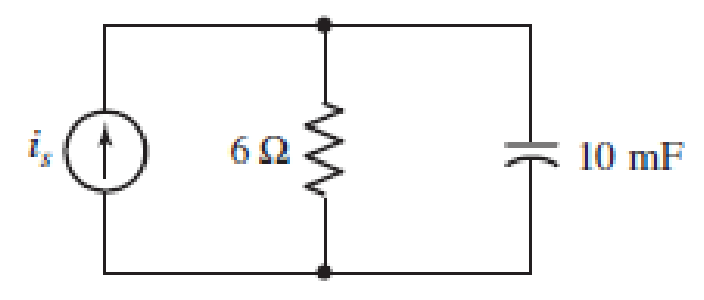
■ FIGURE 11.28
Expert Solution & Answer
Want to see the full answer?
Check out a sample textbook solution
Students have asked these similar questions
The voltage represented by e = 240 Sin(377t) volts is connected across a 20 ohms
resistor. The RMS current indicated by a modern DMM (digital multi-meter) is ...
a) 24 A
O b) 8.49 A
O c) 12 A
O d) 6 A
A sinusoidal alternating voltage of effective value of 250 V and a frequency of 60 hz. It crosses the zero axis in a positive direction when t=0. Determine a) the instantaneous value of voltage after 12.45 msec; b) the time taken to reach 275 V after a period; c) the time to reach a value of 300 V after a passing through maximum positive value.
On one of my many trips to Menards, I purchased a 14 watt LED “soft white" light
bulb with an output of 1600 lumens and provides light output equivalent to a 100 watt incandescent light
bulb. The A19 form factor bulb is designed to operate on a standard 120 V,
60 Hz power line.
rms
Chapter 11 Solutions
Loose Leaf for Engineering Circuit Analysis Format: Loose-leaf
Ch. 11.1 - A current source of 12 cos 2000t A, a 200 ....Ch. 11.2 - Given the phasor voltage across an impedance ,...Ch. 11.2 - Prob. 3PCh. 11.2 - Prob. 4PCh. 11.2 - A voltage source vs is connected across a 4...Ch. 11.3 - If the 30 mH inductor of Example 11.7 is replaced...Ch. 11.4 - Calculate the effective value of each of the...Ch. 11.5 - For the circuit of Fig. 11.16, determine the power...Ch. 11.6 - Prob. 10PCh. 11 - Prob. 1E
Ch. 11 - Determine the power absorbed at t = 1.5 ms by each...Ch. 11 - Calculate the power absorbed at t = 0, t = 0+, and...Ch. 11 - Three elements are connected in parallel: a 1 k...Ch. 11 - Let is = 4u(t) A in the circuit of Fig. 11.28. (a)...Ch. 11 - Prob. 6ECh. 11 - Assuming no transients are present, calculate the...Ch. 11 - Prob. 8ECh. 11 - Prob. 9ECh. 11 - Prob. 10ECh. 11 - The phasor current I=915mA (corresponding to a...Ch. 11 - A phasor voltage V=10045V (the sinusoid operates...Ch. 11 - Prob. 13ECh. 11 - Prob. 14ECh. 11 - Find the average power for each element in the...Ch. 11 - (a) Calculate the average power absorbed by each...Ch. 11 - Prob. 17ECh. 11 - Prob. 18ECh. 11 - Prob. 19ECh. 11 - The circuit in Fig. 11.36 has a series resistance...Ch. 11 - Prob. 21ECh. 11 - Prob. 22ECh. 11 - Prob. 23ECh. 11 - Prob. 24ECh. 11 - Prob. 25ECh. 11 - Prob. 26ECh. 11 - Prob. 27ECh. 11 - Prob. 28ECh. 11 - Prob. 29ECh. 11 - Prob. 30ECh. 11 - Prob. 31ECh. 11 - Prob. 32ECh. 11 - Prob. 33ECh. 11 - (a) Calculate both the average and rms values of...Ch. 11 - Prob. 35ECh. 11 - FIGURE 11.43 Calculate the power factor of the...Ch. 11 - Prob. 37ECh. 11 - Prob. 38ECh. 11 - Prob. 40ECh. 11 - Prob. 41ECh. 11 - Prob. 42ECh. 11 - Prob. 43ECh. 11 - Compute the complex power S (in polar form) drawn...Ch. 11 - Calculate the apparent power, power factor, and...Ch. 11 - Prob. 46ECh. 11 - Prob. 48ECh. 11 - Prob. 49ECh. 11 - Prob. 50ECh. 11 - Prob. 51ECh. 11 - Prob. 52ECh. 11 - FIGURE 11.49 Instead of including a capacitor as...Ch. 11 - Prob. 54ECh. 11 - A load is drawing 10 A rms when connected to a...Ch. 11 - For the circuit of Fig. 11.50, assume the source...Ch. 11 - Prob. 57ECh. 11 - A source 45 sin 32t V is connected in series with...Ch. 11 - Prob. 60ECh. 11 - FIGURE 11.51 The circuit in Fig. 11.51 uses a Pi...Ch. 11 - Prob. 62ECh. 11 - Prob. 63ECh. 11 - You would like to maximize power transfer to a 50 ...
Knowledge Booster


Learn more about
Need a deep-dive on the concept behind this application? Look no further. Learn more about this topic, electrical-engineering and related others by exploring similar questions and additional content below.Similar questions
- The equation for 60 cycles current sine wave having RMS value 30 amperes, will be ____. Kindly provide a CLEAR and COMPLETE solution.#44a. 42.4 sin 120π t Amp b. 30 sin 120t Amp c. 30 sin 60t Amp d. 42,4 sin 60π t Amparrow_forwardFor the circuit of Fig.11.78 composed of standard values: A. Determine the time constant. B. Write the mathematical expression for the current It after the switch is closed C. Repeat part (b) for VL and VR D. Determine il and VL at one three- and five-time constants. E. Sketch the waveforms of iL,VL and VR.arrow_forward%VO 1₁. 1₁. Why transient steady in electric circuits is important ? To know the normal current values passing through the circuit branches To know the voltage of the source To have a steady state case To know the possible greatest stresses on circuit component Y11 for the following circuit is * 0.4 S 0.5 S 3.5 S 0.45 S 592 www 592 0.5V/₂ ۰ ۹:۰۳ ΣΤΩ *arrow_forward
- Given a series circuit comprised of the following element: 81.59-ohm resistor, practical inductor with internal resistance of 0.99 ohm and reactance of 54.29 ohms; and a capacitor with reactance of 6.15 ohms. Compute for equivalent impedance angle in degrees. Note: Follow this reminder carefully. Compute to the nearest 4 decimal places. No Scientific notation. Do not round off in the middle of calculation. Use stored values. Write the numerical values only. No units in your final answer. Spaces are not allowed. Excessive number of decimals as compared to the required number of decimals may result to an incorrect answer.arrow_forwardAn alternating current is represented by the equation: i(t) = 150sin 628t Calculate; 1.The frequency, 2.The period, 3.The ratio of the rms value to the average value, 4. The time taken from t 0 with the function rising positively to reach a magnitude of + 100 A for the second and fifth time 5. The time taken from t = 0 with the function rising positively to reach a magnitude of - 100 A for the first timearrow_forwarda) Write down the expression of instantaneous voltage for an AC voltage having a Peak value of 220 Volts and a frequency of 50 Hz provided at time t=0, the instantaneous voltage is 220 Volts. What is the instantaneous voltage of the source at time “t = 5 seconds” What is its RMS voltage? b) Two 200Ω resistances are connected in series with one 0.5 H Inductance and two 100μF Capacitance with the power supply of part (a). (i)Draw the circuit diagram of the above network (ii)What is the total impedance of the circuit (iii)What is the max current that flows through the Inductance? (iv)What is the max current that flows through each of the Capacitance? (v)What is the power dissipated in the circuit (vi)What is the power factor of the circuit (vii)What is the resonance frequency of the circuit? (viii) What is the maximum power dissipated by the circuit when it is in resonancearrow_forward
- Given a series circuit comprised of the following element: 77.03-ohm resistor, practical inductor with internal resistance of 0.16 ohm and reactance of 74.36 ohms; and a capacitor with reactance of 12.45 ohms. Compute for the magnitude of its equivalent impedance in ohms. Note: Follow this reminder carefully. Compute to the nearest 4 decimal places. No Scientific notation. Do not round off in the middle of calculation. Use stored values.arrow_forwardGiven a series circuit comprised of the following element: 88.01-ohm resistor, practical inductor with internal resistance of 0.76 ohm and reactance of 25.96 ohms; and a capacitor with reactance of 9.53 ohms. Compute for the magnitude of its equivalent impedance in ohms. Note: Follow this reminder carefully. Compute to the nearest 4 decimal places. No Scientific notation. Do not round off in the middle of calculation. Use stored values. Write the numerical values only. No units in your final answer. Spaces are not allowed. Excessive number of decimals as compared to the required number of decimals may result to an incorrect answerarrow_forwardI have already answer but can please help to understand calculations..i will give vote A 240 kV, 3-phase, 50 Hz, 400 km transmission line has a capacitance to earth of 0.04 µF/km per phase. Calculate the inductance and kVA rating of the Peterson coil used for earthing the above system.arrow_forward
- Time left 0: ↑) IZ0A 202V 6 Assuming suitable sign of the complex impedance of the inductor and the capacitor, and for I = 5 Amp, answer the following questions. Magnitude of current through the 6 ohm resistor is Amp Real power consumed by the 6 ohm resistor is Watt Magnitude of voltage across the current source is Voltarrow_forward11.11 Sketch the current waveform for the circuit below given that the breakover potential is 25V and IH = 1mA. 15 V peak 4.7 kNarrow_forwardExample 11.55. The voltage across a 0.01 μF capacitor is 240 sin (1-25 × 10ª t−30%) V. Write the mathematical expression for the current through it.arrow_forward
arrow_back_ios
SEE MORE QUESTIONS
arrow_forward_ios
Recommended textbooks for you
 Introductory Circuit Analysis (13th Edition)Electrical EngineeringISBN:9780133923605Author:Robert L. BoylestadPublisher:PEARSON
 Delmar's Standard Textbook Of ElectricityElectrical EngineeringISBN:9781337900348Author:Stephen L. HermanPublisher:Cengage Learning
 Programmable Logic ControllersElectrical EngineeringISBN:9780073373843Author:Frank D. PetruzellaPublisher:McGraw-Hill Education
 Fundamentals of Electric CircuitsElectrical EngineeringISBN:9780078028229Author:Charles K Alexander, Matthew SadikuPublisher:McGraw-Hill Education
 Electric Circuits. (11th Edition)Electrical EngineeringISBN:9780134746968Author:James W. Nilsson, Susan RiedelPublisher:PEARSON
 Engineering ElectromagneticsElectrical EngineeringISBN:9780078028151Author:Hayt, William H. (william Hart), Jr, BUCK, John A.Publisher:Mcgraw-hill Education,
Introductory Circuit Analysis (13th Edition)
Electrical Engineering
ISBN:9780133923605
Author:Robert L. Boylestad
Publisher:PEARSON
Delmar's Standard Textbook Of Electricity
Electrical Engineering
ISBN:9781337900348
Author:Stephen L. Herman
Publisher:Cengage Learning
Programmable Logic Controllers
Electrical Engineering
ISBN:9780073373843
Author:Frank D. Petruzella
Publisher:McGraw-Hill Education
Fundamentals of Electric Circuits
Electrical Engineering
ISBN:9780078028229
Author:Charles K Alexander, Matthew Sadiku
Publisher:McGraw-Hill Education
Electric Circuits. (11th Edition)
Electrical Engineering
ISBN:9780134746968
Author:James W. Nilsson, Susan Riedel
Publisher:PEARSON
Engineering Electromagnetics
Electrical Engineering
ISBN:9780078028151
Author:Hayt, William H. (william Hart), Jr, BUCK, John A.
Publisher:Mcgraw-hill Education,
02 - Sinusoidal AC Voltage Sources in Circuits, Part 1; Author: Math and Science;https://www.youtube.com/watch?v=8zMiIHVMfaw;License: Standard Youtube License