
Loose Leaf for Engineering Circuit Analysis Format: Loose-leaf
9th Edition
ISBN: 9781259989452
Author: Hayt
Publisher: Mcgraw Hill Publishers
expand_more
expand_more
format_list_bulleted
Videos
Textbook Question
Chapter 3, Problem 10E
The circuit of Fig. 3.53 represents a system comprised of an LED sign powered by a combination of battery storage and three solar panels. The panels are not equally illuminated, so the current each supplies can vary, although the voltage
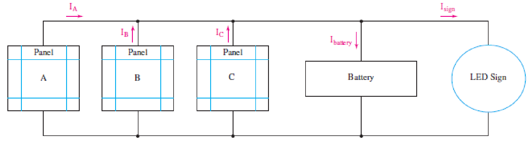
■ FIGURE 3.53
across each is forced to be the same. If IA = 4.5 A, IB = 4.3 A, and IC = 4.6 A, calculate the current flowing into the battery if the LED sign draws 5.1 A.
Expert Solution & Answer
Want to see the full answer?
Check out a sample textbook solution
Students have asked these similar questions
1. A PMMC instrument has internal resistance of 1.7kΩ andgives full scale deflection for 50μA. Calculate the required resistance value of multiplier resistors for employing the meter as a multi range voltmeter for voltage ranges of 10V, 50V and 100V.
R = 4.5KN
| = 5µA
State the ohmmeter scale when the
Im
current is 0A, ½ FSD, ¼ FSD and FSD
V
Ry
Rm = 5000
B
Please show the complete solution. Thank you so much
Voltage Multipliers (electronics)
Chapter 3 Solutions
Loose Leaf for Engineering Circuit Analysis Format: Loose-leaf
Ch. 3.2 - 3.1 (a) Count the number of branches and nodes in...Ch. 3.3 - Determine ix and vx in the circuit of Fig. 3.7....Ch. 3.3 - For the circuit of Fig. 3.9, if vR1=1V, determine...Ch. 3.3 - Determine vx in the circuit of Fig. 3.11.Ch. 3.4 - In the circuit of Fig. 3.12b, vs1 = 120 V, vs2 =...Ch. 3.4 - 3.6 In the circuit of Fig. 3.14, find the power...Ch. 3.5 - Determine v in the circuit of Fig. 3.16.Ch. 3.5 - For the single-node-pair circuit of Fig. 3.18,...Ch. 3.6 - Determine the current i in the circuit of Fig....Ch. 3.6 - Determine the voltage v in the circuit of Fig....
Ch. 3.6 - Determine whether the circuit of Fig. 3.25...Ch. 3.7 - 3.12 Determine a single-value equivalent...Ch. 3.7 - 3.13 Determine i in the circuit of Fig. 3.29....Ch. 3.7 - Determine v in the circuit of Fig. 3.31 by first...Ch. 3.7 - 3.15 For the circuit of Fig. 3.33, calculate the...Ch. 3.8 - 3.16 Use voltage division to determine vx in the...Ch. 3.8 - In the circuit of Fig. 3.40, use resistance...Ch. 3 - Referring to the circuit depicted in Fig. 3.45,...Ch. 3 - Referring to the circuit depicted in Fig. 3.46,...Ch. 3 - For the circuit of Fig. 3.47: (a) Count the number...Ch. 3 - For the circuit of Fig. 3.47: (a) Count the number...Ch. 3 - Refer to the circuit of Fig. 3.48, and answer the...Ch. 3 - A local restaurant has a neon sign constructed...Ch. 3 - Referring to the single-node diagram of Fig. 3.50,...Ch. 3 - Determine the current labeled I in each of the...Ch. 3 - In the circuit shown in Fig. 3.52, the resistor...Ch. 3 - The circuit of Fig. 3.53 represents a system...Ch. 3 - In the circuit depicted in Fig. 3.54, ix is...Ch. 3 - For the circuit of Fig. 3.55 (which employs a...Ch. 3 - Determine the current labeled I3 in the circuit of...Ch. 3 - Study the circuit depicted in Fig. 3.57, and...Ch. 3 - Prob. 15ECh. 3 - For the circuit of Fig. 3.58: (a) Determine the...Ch. 3 - For each of the circuits in Fig. 3.59, determine...Ch. 3 - Use KVL to obtain a numerical value for the...Ch. 3 - Prob. 19ECh. 3 - In the circuit of Fig. 3.55, calculate the voltage...Ch. 3 - Determine the value of vx as labeled in the...Ch. 3 - Consider the simple circuit shown in Fig. 3.63....Ch. 3 - (a) Determine a numerical value for each current...Ch. 3 - The circuit shown in Fig. 3.65 includes a device...Ch. 3 - The circuit of Fig. 3.12b is constructed with the...Ch. 3 - Obtain a numerical value for the power absorbed by...Ch. 3 - Compute the power absorbed by each element of the...Ch. 3 - Compute the power absorbed by each element in the...Ch. 3 - Kirchhoffs laws apply whether or not Ohms law...Ch. 3 - Referring to the circuit of Fig. 3.70, (a)...Ch. 3 - Determine a value for the voltage v as labeled in...Ch. 3 - Referring to the circuit depicted in Fig. 3.72,...Ch. 3 - Determine the voltage v as labeled in Fig. 3.73,...Ch. 3 - Although drawn so that it may not appear obvious...Ch. 3 - Determine the numerical value for veq in Fig....Ch. 3 - Determine the numerical value for ieq in Fig....Ch. 3 - For the circuit presented in Fig. 3.76. determine...Ch. 3 - Determine the value of v1 required to obtain a...Ch. 3 - (a) For the circuit of Fig. 3.78, determine the...Ch. 3 - What value of IS in the circuit of Fig. 3.79 will...Ch. 3 - (a) Determine the values for IX and VY in the...Ch. 3 - Determine the equivalent resistance of each of the...Ch. 3 - For each network depicted in Fig. 3.82, determine...Ch. 3 - (a) Simplify the circuit of Fig. 3.83 as much as...Ch. 3 - (a) Simplify the circuit of Fig. 3.84, using...Ch. 3 - Making appropriate use of resistor combination...Ch. 3 - Calculate the voltage labeled vx in the circuit of...Ch. 3 - Determine the power absorbed by the 15 resistor...Ch. 3 - Calculate the equivalent resistance Req of the...Ch. 3 - Show how to combine four 100 resistors to obtain...Ch. 3 - Prob. 51ECh. 3 - Prob. 52ECh. 3 - Prob. 53ECh. 3 - Prob. 54ECh. 3 - Prob. 55ECh. 3 - Prob. 56ECh. 3 - Prob. 57ECh. 3 - Prob. 58ECh. 3 - Prob. 59ECh. 3 - Prob. 60ECh. 3 - With regard to the circuit shown in Fig. 3.98,...Ch. 3 - Delete the leftmost 10 resistor in the circuit of...Ch. 3 - Consider the seven-element circuit depicted in...
Knowledge Booster


Learn more about
Need a deep-dive on the concept behind this application? Look no further. Learn more about this topic, electrical-engineering and related others by exploring similar questions and additional content below.Similar questions
- The expected value of the voltage across a resistor is ‘A’V. However, measurement yields a value of ‘B’ V. Calculate: a)Absolute error b) Percentage error c) Absolute accuracy d) Relative accuracyarrow_forwardQ3\ Draw the symbols of the following electronic devices. 1- coil, 2- Zener diode, 3- npn transistor, 4- Thermistorarrow_forwardComplete the table of values for this circuit, representing all quantities in complex-number form: C,22 uF 100 mll sV 370 He I pF R, Totalarrow_forward
- In the circuit shown in the figure below, C1=39µF, C2=25µF, C3=22µF, and a voltage Vab=48V is applied accross points a and b. After C1 is fully charged, the switch is thrown to the right. What is the final voltage on C2? Express your answer in units of V(Volts) using one decimal place. C2 C1T C3 b HAEarrow_forwardTwo voltmeter of (0-300 V) range are connected in parallel to a A.C. circuit. One voltmeter is moving iron type reads 200 V. If the other is PMMC instrument, its reading will be a)200 V b) slightly less than 200 V c) 0 Varrow_forward7. If a third resistor (R3), identical to the other two, is added in parallel with the first two, then the electric potential difference (voltage drop) across each of the three individual resistors will a. increase. b. decrease c. remain the same 8. Which of the following statements is true about resistance? (State True or False AND EXPLAIN YOUR REASON AND SHOW CALCULATIONS).arrow_forward
- 1. Design a circuit for each of these acts that adheres to the particular given requirements. (Label all components, including voltage source) Materials: 1 Power source (Battery pack – 4.5 V) Bag of wires 1 Single-throw switch 1 Double-throw switch 5 light bulbs 2 green, 1 red, 1 yellow mini-ziploc baggies - When the single switch is thrown (closed), Lead Singer, Backup Singer 1, and Backup Singer 2’s lights are ALL turned on. - In the middle of the performance, Backup Singer 1’s light unfortunately goes out, and only the Lead Singer remains lit. - If power is cut to the Lead Singer’s light, make sure that both Backup Singers remain lit.arrow_forward11) Draw a circuit diagram with electrical symbols for the figure below. 100 N 50 N 10 µFarrow_forwardExample: Read and solve the given problems. Strictly follow the number of decimal places specified (if not specified, look at the number of decimal places in the given and follow it.) 1. Given an electrical laboratory experiment involving a series circuit with three identical resistors. The applied battery voltage measured was 9.02 V. The three resistors have the following respective voltages: Vi = 2.94V, V2 = 2.93V, and V3 = 2.96 V. Determine the following: a) The experimental total voltage based on the concept of resistances in series b) Is the value in "a" the true or the approximate value c) The true error and absolute error d) The relative true error percentarrow_forward
- A dead battery is charged by connecting it to the live battery of another car with jumper cables (see figure). (Take R = 2.27 01 and r= 0.08 0.) 0,01 Ω 12 V Live battery R 10 V Dead battery Ignition switch Starter (a) Determine the current in the starter. (Enter your answer to at least one decimal place.) A (b) Determine the current in the dead battery, Aarrow_forwardFor a Darsnival device with a moving coil prepared to read the electrical resistance, calculate the value of Rx in the following figure, if the device reading is in the middle of the scale. = 50 µA R= 4.6 k2 Rm =2 k2 R= 1 k2 Ra-500 2 R. E = 15Varrow_forwardFor the circuit shown below, the total power dissipated by the R3 resistor is: Notice that the current was measured to be 2 A. 48V 24W 120V 30 ohms 480 W 120 W 60 W NOVarrow_forward
arrow_back_ios
SEE MORE QUESTIONS
arrow_forward_ios
Recommended textbooks for you
 Introductory Circuit Analysis (13th Edition)Electrical EngineeringISBN:9780133923605Author:Robert L. BoylestadPublisher:PEARSON
 Delmar's Standard Textbook Of ElectricityElectrical EngineeringISBN:9781337900348Author:Stephen L. HermanPublisher:Cengage Learning
 Programmable Logic ControllersElectrical EngineeringISBN:9780073373843Author:Frank D. PetruzellaPublisher:McGraw-Hill Education
 Fundamentals of Electric CircuitsElectrical EngineeringISBN:9780078028229Author:Charles K Alexander, Matthew SadikuPublisher:McGraw-Hill Education
 Electric Circuits. (11th Edition)Electrical EngineeringISBN:9780134746968Author:James W. Nilsson, Susan RiedelPublisher:PEARSON
 Engineering ElectromagneticsElectrical EngineeringISBN:9780078028151Author:Hayt, William H. (william Hart), Jr, BUCK, John A.Publisher:Mcgraw-hill Education,
Introductory Circuit Analysis (13th Edition)
Electrical Engineering
ISBN:9780133923605
Author:Robert L. Boylestad
Publisher:PEARSON
Delmar's Standard Textbook Of Electricity
Electrical Engineering
ISBN:9781337900348
Author:Stephen L. Herman
Publisher:Cengage Learning
Programmable Logic Controllers
Electrical Engineering
ISBN:9780073373843
Author:Frank D. Petruzella
Publisher:McGraw-Hill Education
Fundamentals of Electric Circuits
Electrical Engineering
ISBN:9780078028229
Author:Charles K Alexander, Matthew Sadiku
Publisher:McGraw-Hill Education
Electric Circuits. (11th Edition)
Electrical Engineering
ISBN:9780134746968
Author:James W. Nilsson, Susan Riedel
Publisher:PEARSON
Engineering Electromagnetics
Electrical Engineering
ISBN:9780078028151
Author:Hayt, William H. (william Hart), Jr, BUCK, John A.
Publisher:Mcgraw-hill Education,
[1.2] 8086 Microprocessor Architecture; Author: ThinkX Academy;https://www.youtube.com/watch?v=XX9rDGTBGgQ;License: Standard Youtube License