
Loose Leaf for Engineering Circuit Analysis Format: Loose-leaf
9th Edition
ISBN: 9781259989452
Author: Hayt
Publisher: Mcgraw Hill Publishers
expand_more
expand_more
format_list_bulleted
Concept explainers
Videos
Textbook Question
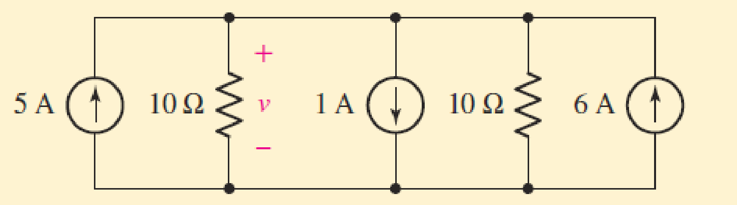
Chapter 3.6, Problem 10P
Determine the voltage v in the circuit of Fig. 3.23 after first replacing the three sources with a single equivalent source.
Expert Solution & Answer
Want to see the full answer?
Check out a sample textbook solution
Students have asked these similar questions
Practice problem 3.2: Find v and i in
eircuit in Figure below.
Answer: -0.2 V, 1.4 A.
42
3 V
ww
7 V
30
22
Biomediča
CHAPTER 3
METHODS OF ANALYSIS
LECTURER: ALI SHABAAN
Practice problem 3.2: Find v and i in the eircuit in Figure below.
Answer: -0.2 V, 1.4 A.
3 V
ww
i
7 V
ww
omediče
Q3) A) A moving-coil instrument gives a f.s.d. when the current is 200 µA and its
resistance is 200 2. Calculate the value of shunt resistance to be connected in
parallel with the meter to enable it to be used as an ammeter for measuring currents
up to 500 mA.
Chapter 3 Solutions
Loose Leaf for Engineering Circuit Analysis Format: Loose-leaf
Ch. 3.2 - 3.1 (a) Count the number of branches and nodes in...Ch. 3.3 - Determine ix and vx in the circuit of Fig. 3.7....Ch. 3.3 - For the circuit of Fig. 3.9, if vR1=1V, determine...Ch. 3.3 - Determine vx in the circuit of Fig. 3.11.Ch. 3.4 - In the circuit of Fig. 3.12b, vs1 = 120 V, vs2 =...Ch. 3.4 - 3.6 In the circuit of Fig. 3.14, find the power...Ch. 3.5 - Determine v in the circuit of Fig. 3.16.Ch. 3.5 - For the single-node-pair circuit of Fig. 3.18,...Ch. 3.6 - Determine the current i in the circuit of Fig....Ch. 3.6 - Determine the voltage v in the circuit of Fig....
Ch. 3.6 - Determine whether the circuit of Fig. 3.25...Ch. 3.7 - 3.12 Determine a single-value equivalent...Ch. 3.7 - 3.13 Determine i in the circuit of Fig. 3.29....Ch. 3.7 - Determine v in the circuit of Fig. 3.31 by first...Ch. 3.7 - 3.15 For the circuit of Fig. 3.33, calculate the...Ch. 3.8 - 3.16 Use voltage division to determine vx in the...Ch. 3.8 - In the circuit of Fig. 3.40, use resistance...Ch. 3 - Referring to the circuit depicted in Fig. 3.45,...Ch. 3 - Referring to the circuit depicted in Fig. 3.46,...Ch. 3 - For the circuit of Fig. 3.47: (a) Count the number...Ch. 3 - For the circuit of Fig. 3.47: (a) Count the number...Ch. 3 - Refer to the circuit of Fig. 3.48, and answer the...Ch. 3 - A local restaurant has a neon sign constructed...Ch. 3 - Referring to the single-node diagram of Fig. 3.50,...Ch. 3 - Determine the current labeled I in each of the...Ch. 3 - In the circuit shown in Fig. 3.52, the resistor...Ch. 3 - The circuit of Fig. 3.53 represents a system...Ch. 3 - In the circuit depicted in Fig. 3.54, ix is...Ch. 3 - For the circuit of Fig. 3.55 (which employs a...Ch. 3 - Determine the current labeled I3 in the circuit of...Ch. 3 - Study the circuit depicted in Fig. 3.57, and...Ch. 3 - Prob. 15ECh. 3 - For the circuit of Fig. 3.58: (a) Determine the...Ch. 3 - For each of the circuits in Fig. 3.59, determine...Ch. 3 - Use KVL to obtain a numerical value for the...Ch. 3 - Prob. 19ECh. 3 - In the circuit of Fig. 3.55, calculate the voltage...Ch. 3 - Determine the value of vx as labeled in the...Ch. 3 - Consider the simple circuit shown in Fig. 3.63....Ch. 3 - (a) Determine a numerical value for each current...Ch. 3 - The circuit shown in Fig. 3.65 includes a device...Ch. 3 - The circuit of Fig. 3.12b is constructed with the...Ch. 3 - Obtain a numerical value for the power absorbed by...Ch. 3 - Compute the power absorbed by each element of the...Ch. 3 - Compute the power absorbed by each element in the...Ch. 3 - Kirchhoffs laws apply whether or not Ohms law...Ch. 3 - Referring to the circuit of Fig. 3.70, (a)...Ch. 3 - Determine a value for the voltage v as labeled in...Ch. 3 - Referring to the circuit depicted in Fig. 3.72,...Ch. 3 - Determine the voltage v as labeled in Fig. 3.73,...Ch. 3 - Although drawn so that it may not appear obvious...Ch. 3 - Determine the numerical value for veq in Fig....Ch. 3 - Determine the numerical value for ieq in Fig....Ch. 3 - For the circuit presented in Fig. 3.76. determine...Ch. 3 - Determine the value of v1 required to obtain a...Ch. 3 - (a) For the circuit of Fig. 3.78, determine the...Ch. 3 - What value of IS in the circuit of Fig. 3.79 will...Ch. 3 - (a) Determine the values for IX and VY in the...Ch. 3 - Determine the equivalent resistance of each of the...Ch. 3 - For each network depicted in Fig. 3.82, determine...Ch. 3 - (a) Simplify the circuit of Fig. 3.83 as much as...Ch. 3 - (a) Simplify the circuit of Fig. 3.84, using...Ch. 3 - Making appropriate use of resistor combination...Ch. 3 - Calculate the voltage labeled vx in the circuit of...Ch. 3 - Determine the power absorbed by the 15 resistor...Ch. 3 - Calculate the equivalent resistance Req of the...Ch. 3 - Show how to combine four 100 resistors to obtain...Ch. 3 - Prob. 51ECh. 3 - Prob. 52ECh. 3 - Prob. 53ECh. 3 - Prob. 54ECh. 3 - Prob. 55ECh. 3 - Prob. 56ECh. 3 - Prob. 57ECh. 3 - Prob. 58ECh. 3 - Prob. 59ECh. 3 - Prob. 60ECh. 3 - With regard to the circuit shown in Fig. 3.98,...Ch. 3 - Delete the leftmost 10 resistor in the circuit of...Ch. 3 - Consider the seven-element circuit depicted in...
Knowledge Booster


Learn more about
Need a deep-dive on the concept behind this application? Look no further. Learn more about this topic, electrical-engineering and related others by exploring similar questions and additional content below.Similar questions
- Determine a valuc for the voltage vas labeled in the circuit of Fig 3.70, and compute the power supplied by the two current sources -2A 100ZR, 3A( R:arrow_forwardPractice problem 3.2: Find v and i in eircuit in Figure below. Answer: -0.2 V, 1.4 A. 3 V 42 7 V METHODS OF ANALYSIS LECTURER: ALI SHABAAN 7 CHAPTER 3 Biomedičaarrow_forwardConsider the circuit diagram in Fig. 3 and Vdc=3V. a) When a-b are short circuited, determine the value of Rv for full scale deflection. b) Find the value of the unknown resistor Rx , if the meter current is 0.33mA.arrow_forward
- 3.7 Apply nodal analysis to solve for Vx in the circuit of Figure 3.56 3.11 Find Vo and the power dissipated in all the resistors in the circuit of Figure 3.60 3.13 Using Nodal analysis , determine Vo in the circuit in Figure 3.61arrow_forward3.32. While constructing a full-wave rectifier, a student mistakenly has swapped the termi- nals of D3 as depicted in Fig. 3.82. Explain what happens. Vin D2 Vout W RL Figure 3.82 DA D3 D₁arrow_forwardComputed (Show complete solutions and redraw as you answer) Using the circuit shown in Fig. 3. 1 and the value of the DC power supply as the theoreticalvalue of the total voltage, compute and record, total current, voltages across each resistor, and currents flowing in each resistor using Voltage and Current Divider Theorem.arrow_forward
- 3.4 For the circuit shown in Fig. 9, the value of R2 is to be measured using the ohmmeter. However, the connection in Fig. 9 does not give the correct value of the resistor. Why? Redraw the circuit showing the true connections. R1 R23 V ohmmeter Figure 9.arrow_forwardB) You are required to analyze the operation of DC circuit shown in Fig.2 and apply Ohm's law and Kirchhoff's voltage and current laws to find all the Voltages (with the associated polarities) and currents (with the associated direction)for all resistors. Test your procedures by simulate the circuit using Multisim to verify your hand calculations (Show all steps, equations, and calculations). IR1 R1 IR6 5.1KO IR3 R6 1ko IR2 ww 2.2KO R3 ww R2 1KO V2 V1 10V 5V IR5 IR7 IR4 1KO 2.2KΩ R7 1kQ R4 R5 Figure 2: DC-Circuit ww wwarrow_forwardFor the network in Fig. 3.12, define a set of state variables and determinethe measurement model. I need detailed solution. Please help me.arrow_forward
- Practice problem 3.2: Find v and i in the eircuit in Figure below. Answer: -0.2 V, 1.4 A. 3 V ww mediča 2Ω wwarrow_forward3.15. Plot the V out as a function of Vx in the cir- cuit of Fig. 3.72. Assume Vx = Vo sin wt and a constant-voltage diode model. + Vx R Vout VB Figure 3.72arrow_forwardFind the value of voltages, v1, V2, V3, V4 and vs in the circuit given below. 67 µF 92 uF valta C1 V4 C2||V2 62 uF vs 132 uF µF V3 C3 112 55 V Csarrow_forward
arrow_back_ios
SEE MORE QUESTIONS
arrow_forward_ios
Recommended textbooks for you
 Introductory Circuit Analysis (13th Edition)Electrical EngineeringISBN:9780133923605Author:Robert L. BoylestadPublisher:PEARSON
 Delmar's Standard Textbook Of ElectricityElectrical EngineeringISBN:9781337900348Author:Stephen L. HermanPublisher:Cengage Learning
 Programmable Logic ControllersElectrical EngineeringISBN:9780073373843Author:Frank D. PetruzellaPublisher:McGraw-Hill Education
 Fundamentals of Electric CircuitsElectrical EngineeringISBN:9780078028229Author:Charles K Alexander, Matthew SadikuPublisher:McGraw-Hill Education
 Electric Circuits. (11th Edition)Electrical EngineeringISBN:9780134746968Author:James W. Nilsson, Susan RiedelPublisher:PEARSON
 Engineering ElectromagneticsElectrical EngineeringISBN:9780078028151Author:Hayt, William H. (william Hart), Jr, BUCK, John A.Publisher:Mcgraw-hill Education,
Introductory Circuit Analysis (13th Edition)
Electrical Engineering
ISBN:9780133923605
Author:Robert L. Boylestad
Publisher:PEARSON
Delmar's Standard Textbook Of Electricity
Electrical Engineering
ISBN:9781337900348
Author:Stephen L. Herman
Publisher:Cengage Learning
Programmable Logic Controllers
Electrical Engineering
ISBN:9780073373843
Author:Frank D. Petruzella
Publisher:McGraw-Hill Education
Fundamentals of Electric Circuits
Electrical Engineering
ISBN:9780078028229
Author:Charles K Alexander, Matthew Sadiku
Publisher:McGraw-Hill Education
Electric Circuits. (11th Edition)
Electrical Engineering
ISBN:9780134746968
Author:James W. Nilsson, Susan Riedel
Publisher:PEARSON
Engineering Electromagnetics
Electrical Engineering
ISBN:9780078028151
Author:Hayt, William H. (william Hart), Jr, BUCK, John A.
Publisher:Mcgraw-hill Education,
Thevenin's Theorem; Author: Neso Academy;https://www.youtube.com/watch?v=veAFVTIpKyM;License: Standard YouTube License, CC-BY