
Loose Leaf for Engineering Circuit Analysis Format: Loose-leaf
9th Edition
ISBN: 9781259989452
Author: Hayt
Publisher: Mcgraw Hill Publishers
expand_more
expand_more
format_list_bulleted
Concept explainers
Videos
Textbook Question
Chapter 3, Problem 16E
For the circuit of Fig. 3.58:
- (a) Determine the voltage v1 if v2 = 0 v3 = −17 V.
- (b) Determine the voltage v1 if v2 = −2 V and v3 = +2 V.
- (c) Determine the voltage v2 if v1 = 7 V and v3 = 9V.
- (d) Determine the voltage v3 if v1 = −2.33V and v2 = −1.70 V.
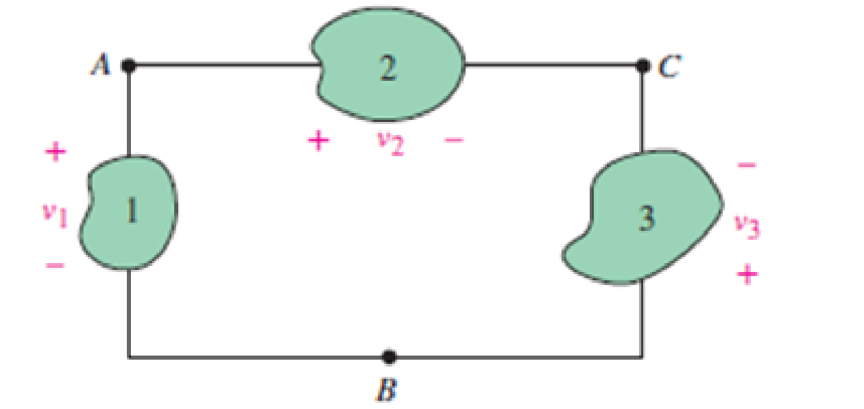
FIGURE 3.58
Expert Solution & Answer
Want to see the full answer?
Check out a sample textbook solution
Students have asked these similar questions
Q3) For the network shown in the figure below, determine the following:
a) fe b) Zinl and Zin2
c) Zo1 and Zo2
d) Avı, Av2, and AVT
+20 V
6.8 kQ
30 ka
6.8 ka
30 ka
0.5 F
0.5 uF
P-150
B- 150
1.5 ka
50 uF
1.5 ka
50 uF
Consider the circuit diagram below. Given I = 2.5 mA and Is = 1.25 mA:
a) Find the currents Is2, I2, I3, I4 and Iz. State your conclusion as a table of values.
b) What is the voltage drop across R7?
c) If Vab = 2.75 V, what is the value of Rs?
Electrical Engineering
For the final problem, consider the following circuit diagram:
12 Q
30 V
Vx
60 Q
2"Vx
B
6) For this circuit, please find and draw:
a. The Thevenin equivalent circuit between A and B, using external excitation to find R.
b. The Norton cquivalent circuit berween A and B.
c. Review section 3-8 from the text. What value load resistor connected between A and B would yield
maximum power transfer? How much power woukd this be?
Chapter 3 Solutions
Loose Leaf for Engineering Circuit Analysis Format: Loose-leaf
Ch. 3.2 - 3.1 (a) Count the number of branches and nodes in...Ch. 3.3 - Determine ix and vx in the circuit of Fig. 3.7....Ch. 3.3 - For the circuit of Fig. 3.9, if vR1=1V, determine...Ch. 3.3 - Determine vx in the circuit of Fig. 3.11.Ch. 3.4 - In the circuit of Fig. 3.12b, vs1 = 120 V, vs2 =...Ch. 3.4 - 3.6 In the circuit of Fig. 3.14, find the power...Ch. 3.5 - Determine v in the circuit of Fig. 3.16.Ch. 3.5 - For the single-node-pair circuit of Fig. 3.18,...Ch. 3.6 - Determine the current i in the circuit of Fig....Ch. 3.6 - Determine the voltage v in the circuit of Fig....
Ch. 3.6 - Determine whether the circuit of Fig. 3.25...Ch. 3.7 - 3.12 Determine a single-value equivalent...Ch. 3.7 - 3.13 Determine i in the circuit of Fig. 3.29....Ch. 3.7 - Determine v in the circuit of Fig. 3.31 by first...Ch. 3.7 - 3.15 For the circuit of Fig. 3.33, calculate the...Ch. 3.8 - 3.16 Use voltage division to determine vx in the...Ch. 3.8 - In the circuit of Fig. 3.40, use resistance...Ch. 3 - Referring to the circuit depicted in Fig. 3.45,...Ch. 3 - Referring to the circuit depicted in Fig. 3.46,...Ch. 3 - For the circuit of Fig. 3.47: (a) Count the number...Ch. 3 - For the circuit of Fig. 3.47: (a) Count the number...Ch. 3 - Refer to the circuit of Fig. 3.48, and answer the...Ch. 3 - A local restaurant has a neon sign constructed...Ch. 3 - Referring to the single-node diagram of Fig. 3.50,...Ch. 3 - Determine the current labeled I in each of the...Ch. 3 - In the circuit shown in Fig. 3.52, the resistor...Ch. 3 - The circuit of Fig. 3.53 represents a system...Ch. 3 - In the circuit depicted in Fig. 3.54, ix is...Ch. 3 - For the circuit of Fig. 3.55 (which employs a...Ch. 3 - Determine the current labeled I3 in the circuit of...Ch. 3 - Study the circuit depicted in Fig. 3.57, and...Ch. 3 - Prob. 15ECh. 3 - For the circuit of Fig. 3.58: (a) Determine the...Ch. 3 - For each of the circuits in Fig. 3.59, determine...Ch. 3 - Use KVL to obtain a numerical value for the...Ch. 3 - Prob. 19ECh. 3 - In the circuit of Fig. 3.55, calculate the voltage...Ch. 3 - Determine the value of vx as labeled in the...Ch. 3 - Consider the simple circuit shown in Fig. 3.63....Ch. 3 - (a) Determine a numerical value for each current...Ch. 3 - The circuit shown in Fig. 3.65 includes a device...Ch. 3 - The circuit of Fig. 3.12b is constructed with the...Ch. 3 - Obtain a numerical value for the power absorbed by...Ch. 3 - Compute the power absorbed by each element of the...Ch. 3 - Compute the power absorbed by each element in the...Ch. 3 - Kirchhoffs laws apply whether or not Ohms law...Ch. 3 - Referring to the circuit of Fig. 3.70, (a)...Ch. 3 - Determine a value for the voltage v as labeled in...Ch. 3 - Referring to the circuit depicted in Fig. 3.72,...Ch. 3 - Determine the voltage v as labeled in Fig. 3.73,...Ch. 3 - Although drawn so that it may not appear obvious...Ch. 3 - Determine the numerical value for veq in Fig....Ch. 3 - Determine the numerical value for ieq in Fig....Ch. 3 - For the circuit presented in Fig. 3.76. determine...Ch. 3 - Determine the value of v1 required to obtain a...Ch. 3 - (a) For the circuit of Fig. 3.78, determine the...Ch. 3 - What value of IS in the circuit of Fig. 3.79 will...Ch. 3 - (a) Determine the values for IX and VY in the...Ch. 3 - Determine the equivalent resistance of each of the...Ch. 3 - For each network depicted in Fig. 3.82, determine...Ch. 3 - (a) Simplify the circuit of Fig. 3.83 as much as...Ch. 3 - (a) Simplify the circuit of Fig. 3.84, using...Ch. 3 - Making appropriate use of resistor combination...Ch. 3 - Calculate the voltage labeled vx in the circuit of...Ch. 3 - Determine the power absorbed by the 15 resistor...Ch. 3 - Calculate the equivalent resistance Req of the...Ch. 3 - Show how to combine four 100 resistors to obtain...Ch. 3 - Prob. 51ECh. 3 - Prob. 52ECh. 3 - Prob. 53ECh. 3 - Prob. 54ECh. 3 - Prob. 55ECh. 3 - Prob. 56ECh. 3 - Prob. 57ECh. 3 - Prob. 58ECh. 3 - Prob. 59ECh. 3 - Prob. 60ECh. 3 - With regard to the circuit shown in Fig. 3.98,...Ch. 3 - Delete the leftmost 10 resistor in the circuit of...Ch. 3 - Consider the seven-element circuit depicted in...
Knowledge Booster


Learn more about
Need a deep-dive on the concept behind this application? Look no further. Learn more about this topic, electrical-engineering and related others by exploring similar questions and additional content below.Similar questions
- 3. Research on the Thevenin's and Norton's theorem and their relations. Write those findings. 4. Derive the equation for VTH for circuit in Figure 3. 5. Derive the equation for RTH for circuit in Figure 3. 6. Derive the equation for IN for circuit in Figure 3. R6 m A 220 ohms R1 V1 R4 m 820 ohms 330 ohms 10 V R2 V2 560 ohms B R5 m vo 1 kohms 470 ohms 5 V FIGURE 3 R3arrow_forwardQ3) For the network shown in the figure below, determine the following: a) re b) Zini and Zinz c) Zoj and Zo2 d) Av1, Av2, and AvT +20 V 6.8 ka 30 kQ 6.8 ka 30 ka 0.5 pF 0.5 uF 1150 B-150 1.5 ka 50 uF 1.5 ka 50 uFarrow_forwardmponent of nódal ch element. There is no way of knowing the current through wever, KCL must be satisfied at a sunernode like any other node. Hence a tde spernode in Fig. 3.5, i + i4 = i2 + i3 (3.11a) v1 - v2 v1 - v3 v2 – 0 v3 - 0 (3.11b) 6. To apply Kirchhoff's voltage law to the supernode in Fig. 3.4 we redraw the circuit as shown in Fig. 3.5. Going around the loop in the clockwise»direction gives -V2 + 5 + v3 = 0=v2 – V3 = 5 (3.12) From Eqs. (3.10), (3.11b), and (3.12), we obtain the node volltages. 5V د مُسق ک من ؤ Figure 3.5 Applying KVL to a supernode. Example 3.2: For the circuit shown in Fig. 3.6, find the node voltages. Solution: The supernode contains the 2-V source, nodes 1 and 10 2 www 2, and the 10-2 resistor. Applying KCL to the 2 V supernode as shown in Fig. 3.7(a) gives 2. 12 2 = i + iz +7 7 A Expressing in and iz in terms of the node voltages 2 A 22 v1 - 0 v2 - 0 2 = 7 4 or (3.2.1) V2 =-20 - 2vVI Figure 3.6 For Example 3.2. ESTHRER: ALI SHARAAN METHORS OF ANALYSIS…arrow_forward
- R. Vi (i VL In the circuit pictured, R1 = 8090N R2 = 550N R3 = 1820N R, = 40002 Vị = 84.5V 4 = 0.0084 A Use Thevenin's theorem to calculate, a.) Vin b.) Rth c.) the voltage across Rth d.) VI, e.) If you could replace R1 with any resistance value, calculate the value you would choose to deliver maximum power to the R1.arrow_forwardNetwork 2R R 3V 2R -1.5 mA A network is implemented with three resistors and a voltage source as shown above. Its terminal characteristics are also given graphically above. From the graphical data given above, determine Thevenin equivalent voltage in volts for the network. Your Answer: Answerarrow_forwardelectrical engineering Find V1, V2, V3, and V4. choices a.) V1= 10 V, V2= 9.278 V, V3= 8.1 V; V4= 9.817 V b.) V1= 11.9 V, V2= 9.1 V, V3= 8.1 V; V4= 9.817 V c.) V1= 10 V, V2= 9.1 V, V3= 3.271 V; V4= 9.817 V d.) V1= 10 V, V2= 1.367 V, V3= 8.1 V; V4= 9.817 V e.) V1= 10 V, V2= 9.1 V, V3= 3.41 V; V4= 9.817 V f.) V1= 10 V, V2= 5.1 V, V3= 1.1 V; V4= 3.817 V g.) V1= 10 V, V2= 6.28 V, V3= 4.884 V; V4= 5.001 Varrow_forward
- In the circuit shown, determine the following: a.) The voltage Vab is V ( a.) 8 ( b) 8.5 (c) 6.5 (d) 7.5 (e) 7 b.) The current through E1 is about A. (a) 2.333 (b)1.333 (c) 0.1333 (d) 0.666 (e) 1.666 c.) The current through E3 is about А. (a) 2.333 (b)1.333 (c) 0.1333 (d) 0.666 (e) 1.666 d.) The current through the 4 ohms resistance is about A. (a) 2.125 (b) 1.75 (c) 2.0 (d) 2.125 (e) 1.625 e.) The current through E4 is about А. (a) 1.333 (b) 1.0 (c) 5.0 (d) 3.666 (e) 4.333arrow_forwardAccording to the circuit and parameters given in the figure, make your calculations and write the table. wmww w n ww bbn m w w w w Please fill in. www ww w +12V +12V M1 M2 2kN 10kN K ImA/V² 0.5mA/V² VTH 2V 1.5V 22kN M2 MODE 33k2 M1 Ip 1kN VGS Vps K1=lmA/V² Vth1=2V; M2: K2=0.5mA/V² VTH2=1.5Varrow_forwardExample For the test circuit below, calculate the following:VB1 VE1 VB2 VE2 IE2 OHI INPUT CC1 680nF R₁ 47k R₂ VB1 13k RCL 5k1 TR1 REI 2k0 VB2 TR2 RE2 1k8 Cc2 10uF IVE2 +12V DC R₂ 10k R4 51R OUTPUTarrow_forward
- Q2:For the network of figure ,determine: a-Vc,VB, VE,Ic,VCE and IB b- Determine the net change in Ic if a change in operating condition result in Ico increasing from 0.2µA to 10 µA, VBE drops from 0.7 V to 0.5 V and B increase 25%. c-Determine the net change in Ic if a change in temperature from 25C°-85C°and Ico increasing from 0.2µA to 10 µA, VBE drops from 0.7 V to 0.5 v. 2.2 Kongb uF 510 KOhm 10 UF HH 1 kOhm B=250 10 mv 1.8Kohmarrow_forwardFor the given figure below, answer the following. 1. Resistor values in ohms.2. Use nodal analysis to determine V1, V2, and V3.3. Use mesh analysis to determine IS and Ix.arrow_forwardR1 D1 D2 R2 V1 V3 R3 V2 Rj=120 Q, R2=10 Q and R3=200 2, Vi= 10V and V2=15V, Dị and D2 (forward voltage drop) VF=0.8V a) Using mesh analysis to analyze the given circuit, derive the voltage V3. b) What is the state operation of Di and D2?arrow_forward
arrow_back_ios
SEE MORE QUESTIONS
arrow_forward_ios
Recommended textbooks for you
 Introductory Circuit Analysis (13th Edition)Electrical EngineeringISBN:9780133923605Author:Robert L. BoylestadPublisher:PEARSON
 Delmar's Standard Textbook Of ElectricityElectrical EngineeringISBN:9781337900348Author:Stephen L. HermanPublisher:Cengage Learning
 Programmable Logic ControllersElectrical EngineeringISBN:9780073373843Author:Frank D. PetruzellaPublisher:McGraw-Hill Education
 Fundamentals of Electric CircuitsElectrical EngineeringISBN:9780078028229Author:Charles K Alexander, Matthew SadikuPublisher:McGraw-Hill Education
 Electric Circuits. (11th Edition)Electrical EngineeringISBN:9780134746968Author:James W. Nilsson, Susan RiedelPublisher:PEARSON
 Engineering ElectromagneticsElectrical EngineeringISBN:9780078028151Author:Hayt, William H. (william Hart), Jr, BUCK, John A.Publisher:Mcgraw-hill Education,
Introductory Circuit Analysis (13th Edition)
Electrical Engineering
ISBN:9780133923605
Author:Robert L. Boylestad
Publisher:PEARSON
Delmar's Standard Textbook Of Electricity
Electrical Engineering
ISBN:9781337900348
Author:Stephen L. Herman
Publisher:Cengage Learning
Programmable Logic Controllers
Electrical Engineering
ISBN:9780073373843
Author:Frank D. Petruzella
Publisher:McGraw-Hill Education
Fundamentals of Electric Circuits
Electrical Engineering
ISBN:9780078028229
Author:Charles K Alexander, Matthew Sadiku
Publisher:McGraw-Hill Education
Electric Circuits. (11th Edition)
Electrical Engineering
ISBN:9780134746968
Author:James W. Nilsson, Susan Riedel
Publisher:PEARSON
Engineering Electromagnetics
Electrical Engineering
ISBN:9780078028151
Author:Hayt, William H. (william Hart), Jr, BUCK, John A.
Publisher:Mcgraw-hill Education,
Thevenin's Theorem; Author: Neso Academy;https://www.youtube.com/watch?v=veAFVTIpKyM;License: Standard YouTube License, CC-BY