
Loose Leaf for Engineering Circuit Analysis Format: Loose-leaf
9th Edition
ISBN: 9781259989452
Author: Hayt
Publisher: Mcgraw Hill Publishers
expand_more
expand_more
format_list_bulleted
Videos
Textbook Question
Chapter 3, Problem 45E
(a) Simplify the circuit of Fig. 3.84, using appropriate source and resistor combinations. (b) Determine the voltage labeled v, using your simplified circuit. (c) Calculate the power provided by the 2 A source to the rest of the circuit.
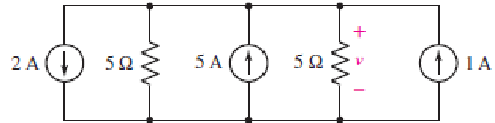
■ FIGURE 3.84
Expert Solution & Answer
Want to see the full answer?
Check out a sample textbook solution
Students have asked these similar questions
In Figure 3, the components are found to have the values: R1 = 50 ohms; R2 = 30 ohms; R3
= 45 ohms; Ea = 100 volts; Eb = 100 volts. (a) Using the procedures in Part B- Superposition
Theorem, identify the values of all currents and show the details of your simulations. (b)
What would be the results if one of the sources, say Eb, was reversed in the circuit? Verify
your answer through simulation.
Analyze the circuit to determine the unknown voltages.
routes:
type:
combination v
b. 200
V
www
unit
unit
unit
unit
6V
source
n/a
a
a. 200
C. 200
check answers
cannot be determ
final review, circuit analysis
Scientific Online Calculator
=9,81m/s, v.ound= 343m/s
www
www
a) For the circuit shown in Figure (3.a), find i, using any method.
9kQ
12kn
12k0
6kn
12v
6y
i,
Figure 3.a
Chapter 3 Solutions
Loose Leaf for Engineering Circuit Analysis Format: Loose-leaf
Ch. 3.2 - 3.1 (a) Count the number of branches and nodes in...Ch. 3.3 - Determine ix and vx in the circuit of Fig. 3.7....Ch. 3.3 - For the circuit of Fig. 3.9, if vR1=1V, determine...Ch. 3.3 - Determine vx in the circuit of Fig. 3.11.Ch. 3.4 - In the circuit of Fig. 3.12b, vs1 = 120 V, vs2 =...Ch. 3.4 - 3.6 In the circuit of Fig. 3.14, find the power...Ch. 3.5 - Determine v in the circuit of Fig. 3.16.Ch. 3.5 - For the single-node-pair circuit of Fig. 3.18,...Ch. 3.6 - Determine the current i in the circuit of Fig....Ch. 3.6 - Determine the voltage v in the circuit of Fig....
Ch. 3.6 - Determine whether the circuit of Fig. 3.25...Ch. 3.7 - 3.12 Determine a single-value equivalent...Ch. 3.7 - 3.13 Determine i in the circuit of Fig. 3.29....Ch. 3.7 - Determine v in the circuit of Fig. 3.31 by first...Ch. 3.7 - 3.15 For the circuit of Fig. 3.33, calculate the...Ch. 3.8 - 3.16 Use voltage division to determine vx in the...Ch. 3.8 - In the circuit of Fig. 3.40, use resistance...Ch. 3 - Referring to the circuit depicted in Fig. 3.45,...Ch. 3 - Referring to the circuit depicted in Fig. 3.46,...Ch. 3 - For the circuit of Fig. 3.47: (a) Count the number...Ch. 3 - For the circuit of Fig. 3.47: (a) Count the number...Ch. 3 - Refer to the circuit of Fig. 3.48, and answer the...Ch. 3 - A local restaurant has a neon sign constructed...Ch. 3 - Referring to the single-node diagram of Fig. 3.50,...Ch. 3 - Determine the current labeled I in each of the...Ch. 3 - In the circuit shown in Fig. 3.52, the resistor...Ch. 3 - The circuit of Fig. 3.53 represents a system...Ch. 3 - In the circuit depicted in Fig. 3.54, ix is...Ch. 3 - For the circuit of Fig. 3.55 (which employs a...Ch. 3 - Determine the current labeled I3 in the circuit of...Ch. 3 - Study the circuit depicted in Fig. 3.57, and...Ch. 3 - Prob. 15ECh. 3 - For the circuit of Fig. 3.58: (a) Determine the...Ch. 3 - For each of the circuits in Fig. 3.59, determine...Ch. 3 - Use KVL to obtain a numerical value for the...Ch. 3 - Prob. 19ECh. 3 - In the circuit of Fig. 3.55, calculate the voltage...Ch. 3 - Determine the value of vx as labeled in the...Ch. 3 - Consider the simple circuit shown in Fig. 3.63....Ch. 3 - (a) Determine a numerical value for each current...Ch. 3 - The circuit shown in Fig. 3.65 includes a device...Ch. 3 - The circuit of Fig. 3.12b is constructed with the...Ch. 3 - Obtain a numerical value for the power absorbed by...Ch. 3 - Compute the power absorbed by each element of the...Ch. 3 - Compute the power absorbed by each element in the...Ch. 3 - Kirchhoffs laws apply whether or not Ohms law...Ch. 3 - Referring to the circuit of Fig. 3.70, (a)...Ch. 3 - Determine a value for the voltage v as labeled in...Ch. 3 - Referring to the circuit depicted in Fig. 3.72,...Ch. 3 - Determine the voltage v as labeled in Fig. 3.73,...Ch. 3 - Although drawn so that it may not appear obvious...Ch. 3 - Determine the numerical value for veq in Fig....Ch. 3 - Determine the numerical value for ieq in Fig....Ch. 3 - For the circuit presented in Fig. 3.76. determine...Ch. 3 - Determine the value of v1 required to obtain a...Ch. 3 - (a) For the circuit of Fig. 3.78, determine the...Ch. 3 - What value of IS in the circuit of Fig. 3.79 will...Ch. 3 - (a) Determine the values for IX and VY in the...Ch. 3 - Determine the equivalent resistance of each of the...Ch. 3 - For each network depicted in Fig. 3.82, determine...Ch. 3 - (a) Simplify the circuit of Fig. 3.83 as much as...Ch. 3 - (a) Simplify the circuit of Fig. 3.84, using...Ch. 3 - Making appropriate use of resistor combination...Ch. 3 - Calculate the voltage labeled vx in the circuit of...Ch. 3 - Determine the power absorbed by the 15 resistor...Ch. 3 - Calculate the equivalent resistance Req of the...Ch. 3 - Show how to combine four 100 resistors to obtain...Ch. 3 - Prob. 51ECh. 3 - Prob. 52ECh. 3 - Prob. 53ECh. 3 - Prob. 54ECh. 3 - Prob. 55ECh. 3 - Prob. 56ECh. 3 - Prob. 57ECh. 3 - Prob. 58ECh. 3 - Prob. 59ECh. 3 - Prob. 60ECh. 3 - With regard to the circuit shown in Fig. 3.98,...Ch. 3 - Delete the leftmost 10 resistor in the circuit of...Ch. 3 - Consider the seven-element circuit depicted in...
Knowledge Booster


Learn more about
Need a deep-dive on the concept behind this application? Look no further. Learn more about this topic, electrical-engineering and related others by exploring similar questions and additional content below.Similar questions
- Q3) A) A moving-coil instrument gives a f.s.d. when the current is 200 µA and its resistance is 200 2. Calculate the value of shunt resistance to be connected in parallel with the meter to enable it to be used as an ammeter for measuring currents up to 500 mA.arrow_forwardDr. Yaseen H. Tahir Example: a) Convert the current souree of Figure below to an equivalent voltage source. 6) Prove your answer. (Home work) 1. 5 mA 10K2 20K2arrow_forward1. Determine the following: (a) .o be Total Current and Total LEC Power of the circuit; (b) the VA = 120 V current passing through each resistors; (c) The voltage drop across each resistors; (d) the power taken by each resistor. R = 30 2 . MERVAN P, DE MOHAMMEI I = ? R3 = 50 2 So oti 13 =? st given to the earer, for this work to be presented or R, = 40 2 LECTURE SLIDE O MEVIN ,OHAJAME SLIDE ON I PEMOHAMM R4 = 60 2 14 = ? ork to be presented or shown to others. + Rs = 60 2 shown to ohers. er, for this work to be pre Cthers. rthis work to be presented or shown R = 70 2 I6 = ? co the hown to others. 1, = ? TURE SLIDES MOHAMN R, = 80 2 CONSENT wasot given to the bearer, for this work to farrow_forward
- Calculate the equivalent voltage in the given below: (Type the numerical value only) B1 = 6.49 V; B2 = 10.52 V; B3 = 9.16 V; B4 = 13.45 V DC SOURCES IN SERIES NUMBER 1 [B1] V HANDEPREL [B2] V OFF [B3] V Equivalent Voltage: OFF 0. CE [B4] V Round your answer to 2 decimal places.arrow_forward7. If a third resistor (R3), identical to the other two, is added in parallel with the first two, then the electric potential difference (voltage drop) across each of the three individual resistors will a. increase. b. decrease c. remain the same 8. Which of the following statements is true about resistance? (State True or False AND EXPLAIN YOUR REASON AND SHOW CALCULATIONS).arrow_forwarda) Using the circuit schematic, find a set of three equations that will allow you to solve for the three currents. b) What are the currents if Ԑ1=28 V, Ԑ2=9 V, R1=177 Ω, R2=293 Ω, R3=326 Ω, and R4=104 Ω. ? To continue, please enter the result of I3 in units of A. Round your answer to 3 decimal placesarrow_forward
- A circuit composed of a 24-V battery and four resistors connected in a series connection, whose resistance are 110, 180, 220, and 250, respectively. Find a) total resistance of the system, b) the total current supplied by the battery and c) voltage across each resistor. (Express your answer in at least 2 decimal places)arrow_forwardPART 1: In this part, you will determine the Thevenin equivalent circuit parameters through computation. a. Determine the Thevenin equivalent circuit of Figure 3.1 between nodes A and B and record all parameters in Table 3.1 under the Calculated Value column. 752 1502 A 5V (+ 2202 4702 Figure 3.1: Determining the Thevenin Equivalent Circuit Calculated Value Vih (V) Isc (mA) Rth (2) Just the calculated value B.arrow_forward21, R2 Va k V3 R1 2A 4V Ve For the above circuit, with R = 7Ohms and R,= 2 0hms, use nodal analysis to determine the voltage at the node V, in Volts. Round your answer to the nearest single digit decimal place. For example, if you calculate 3.27 Volts, then enter 3.3 as your answer. Moving to another question will save this response. o|自 2Type here to searcharrow_forward
- Q3) A) Find RAB for the circuit shown in Figure 3. A O 4 N 50 Figure 3arrow_forward3. Usmg sorce transformation convert the voltage source to current source for the circuit shown m Figure 3 (with Group Discussion wse maximum time 3 Minutes) 4 Ohms 50 V 6 Ohms B Figure 3: ited States)arrow_forwardA circuit composed of a 24-V battery and four resistors connected in a series connection, whose resistance are 110, 180, 220, and 250, respectively. Find a) total resistance of the system, b) the total current supplied by the battery and c) voltage across each resistor. (Express your answer in at least 2 decimal places) Show your solutions and explain.arrow_forward
arrow_back_ios
SEE MORE QUESTIONS
arrow_forward_ios
Recommended textbooks for you
 Introductory Circuit Analysis (13th Edition)Electrical EngineeringISBN:9780133923605Author:Robert L. BoylestadPublisher:PEARSON
 Delmar's Standard Textbook Of ElectricityElectrical EngineeringISBN:9781337900348Author:Stephen L. HermanPublisher:Cengage Learning
 Programmable Logic ControllersElectrical EngineeringISBN:9780073373843Author:Frank D. PetruzellaPublisher:McGraw-Hill Education
 Fundamentals of Electric CircuitsElectrical EngineeringISBN:9780078028229Author:Charles K Alexander, Matthew SadikuPublisher:McGraw-Hill Education
 Electric Circuits. (11th Edition)Electrical EngineeringISBN:9780134746968Author:James W. Nilsson, Susan RiedelPublisher:PEARSON
 Engineering ElectromagneticsElectrical EngineeringISBN:9780078028151Author:Hayt, William H. (william Hart), Jr, BUCK, John A.Publisher:Mcgraw-hill Education,
Introductory Circuit Analysis (13th Edition)
Electrical Engineering
ISBN:9780133923605
Author:Robert L. Boylestad
Publisher:PEARSON
Delmar's Standard Textbook Of Electricity
Electrical Engineering
ISBN:9781337900348
Author:Stephen L. Herman
Publisher:Cengage Learning
Programmable Logic Controllers
Electrical Engineering
ISBN:9780073373843
Author:Frank D. Petruzella
Publisher:McGraw-Hill Education
Fundamentals of Electric Circuits
Electrical Engineering
ISBN:9780078028229
Author:Charles K Alexander, Matthew Sadiku
Publisher:McGraw-Hill Education
Electric Circuits. (11th Edition)
Electrical Engineering
ISBN:9780134746968
Author:James W. Nilsson, Susan Riedel
Publisher:PEARSON
Engineering Electromagnetics
Electrical Engineering
ISBN:9780078028151
Author:Hayt, William H. (william Hart), Jr, BUCK, John A.
Publisher:Mcgraw-hill Education,
[1.2] 8086 Microprocessor Architecture; Author: ThinkX Academy;https://www.youtube.com/watch?v=XX9rDGTBGgQ;License: Standard Youtube License