
Loose Leaf for Engineering Circuit Analysis Format: Loose-leaf
9th Edition
ISBN: 9781259989452
Author: Hayt
Publisher: Mcgraw Hill Publishers
expand_more
expand_more
format_list_bulleted
Videos
Textbook Question
thumb_up100%
Chapter 6, Problem 21E
Referring to Fig. 6.49, sketch vout as a function of (a) vin over the range of −2 V ≤ vin ≤ +2 V, if R4 = 2 kΩ; (b) R4 over the range of 1 kΩ ≤ R4 ≤ 10 kΩ, if vin = 300 mV.
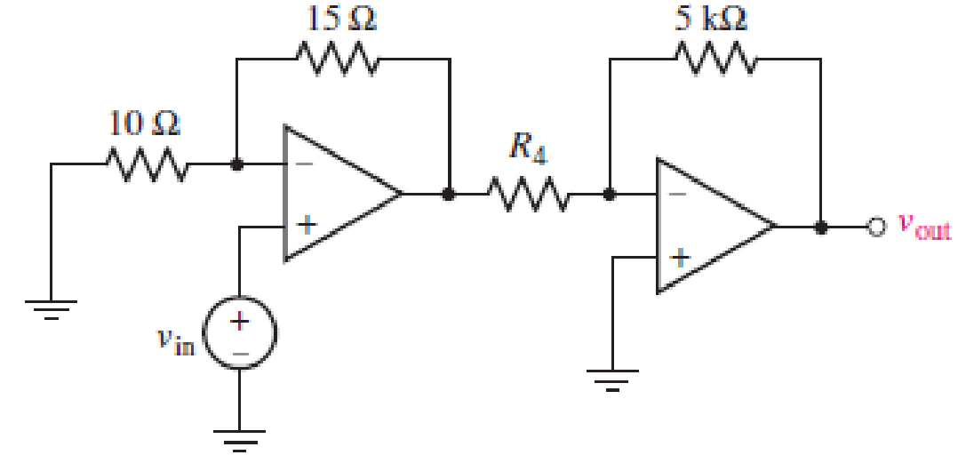
■ FIGURE 6.49
Expert Solution & Answer
Want to see the full answer?
Check out a sample textbook solution
Students have asked these similar questions
6.51 Determine Leg at terminals a-b of the circuit in
Fig. 6.73.
10 mH
elll
60 mH
25 mH
20 mH
all
b
ell
30 mH
ll
Figure 6.73
6.13 Find the voltage across the capacitors in the circuit
of Fig. 6.49 under dc conditions.
10 Q
50 Ω
20 Q
+
40 Ω
C =
C2
60 V
Figure 6.49
6.19
Obtain the equivalent capacitance of the circuit in
Fig. 6.54.
35 μF
Figure 6.54
40 μF
10 μF
10 μF
20 μF
15 μF 15 μF
For Prob. 6.19.
b
5 μF
HH
Chapter 6 Solutions
Loose Leaf for Engineering Circuit Analysis Format: Loose-leaf
Ch. 6.2 - Derive an expression for vout in terms of vin for...Ch. 6.2 - Prob. 2PCh. 6.3 - An historic bridge is showing signs of...Ch. 6.4 - Design a circuit that provides a 12 V output if a...Ch. 6.4 - Design a noninverting Schmitt trigger that that...Ch. 6.5 - Assuming a finite open-loop gain (A), a finite...Ch. 6.5 - Use SPICE to simulate a voltage follower using an...Ch. 6 - For the op amp circuit shown in Fig. 6.39,...Ch. 6 - FIGURE 6.39 Determine the power dissipated by a...Ch. 6 - For the circuit of Fig. 6.40, calculate vout if...
Ch. 6 - For the circuit in Fig. 6.40, find the values of...Ch. 6 - (a) Design a circuit which converts a voltage...Ch. 6 - Prob. 6ECh. 6 - For the circuit of Fig. 6.40, R1 = RL = 50 ....Ch. 6 - Prob. 8ECh. 6 - (a) Design a circuit using only a single op amp...Ch. 6 - Prob. 11ECh. 6 - Determine the output voltage v0 and the current...Ch. 6 - Prob. 13ECh. 6 - Prob. 14ECh. 6 - Prob. 15ECh. 6 - Prob. 16ECh. 6 - Consider the amplifier circuit shown in Fig. 6.46....Ch. 6 - Prob. 18ECh. 6 - Prob. 19ECh. 6 - Prob. 20ECh. 6 - Referring to Fig. 6.49, sketch vout as a function...Ch. 6 - Repeat Exercise 21 using a parameter sweep in...Ch. 6 - Obtain an expression for vout as labeled in the...Ch. 6 - Prob. 24ECh. 6 - Prob. 25ECh. 6 - Prob. 26ECh. 6 - Prob. 27ECh. 6 - Prob. 28ECh. 6 - Prob. 29ECh. 6 - Prob. 30ECh. 6 - Prob. 31ECh. 6 - Determine the value of Vout for the circuit in...Ch. 6 - Calculate V0 for the circuit in Fig. 6.55. FIGURE...Ch. 6 - Prob. 34ECh. 6 - The temperature alarm circuit in Fig. 6.56...Ch. 6 - Prob. 36ECh. 6 - For the circuit depicted in Fig. 6.57, sketch the...Ch. 6 - For the circuit depicted in Fig. 6.58, (a) sketch...Ch. 6 - For the circuit depicted in Fig. 6.59, sketch the...Ch. 6 - In digital logic applications, a +5 V signal...Ch. 6 - Using the temperature sensor in the circuit in...Ch. 6 - Examine the comparator Schmitt trigger circuit in...Ch. 6 - Design the circuit values for the single supply...Ch. 6 - For the instrumentation amplifier shown in Fig....Ch. 6 - A common application for instrumentation...Ch. 6 - (a) Employ the parameters listed in Table 6.3 for...Ch. 6 - Prob. 49ECh. 6 - For the circuit of Fig. 6.62, calculate the...Ch. 6 - Prob. 51ECh. 6 - FIGURE 6.63 (a) For the circuit of Fig. 6.63, if...Ch. 6 - The difference amplifier circuit in Fig. 6.32 has...Ch. 6 - Prob. 55ECh. 6 - Prob. 56ECh. 6 - Prob. 57ECh. 6 - Prob. 58ECh. 6 - Prob. 59ECh. 6 - Prob. 60ECh. 6 - A fountain outside a certain office building is...Ch. 6 - For the circuit of Fig. 6.44, let all resistor...
Knowledge Booster


Learn more about
Need a deep-dive on the concept behind this application? Look no further. Learn more about this topic, electrical-engineering and related others by exploring similar questions and additional content below.Similar questions
- Practice Problem 6. Find the voltage across each of the capacitors in Fig. 6.20. 40 μF 60 µF Answer: U= 45 V, U2 = 45 V, v3 = 15 V, v4 30 V. + 1 - + v3 - 90 V 20 μF 30 V4 Figure 6.20 For Practice Prob. 6.7.arrow_forward6.48 Under steady-state dc conditions, find i and v in the circuit in Fig. 6.71. 5 mA Figure 6.71 For Prob. 6.48. i 2mH 30 ΚΩ 20 ΚΩ 6 μF Iarrow_forwardFind the equivalent capacitance seen at the terminals of the circuit in Fig. 6.17. Answer: 40 μF. Practice Problem 6.6 Cea 50 μF 70 μF 60 μF HH 20 μF Figure 6.17 For Practice Prob. 6.6. 120 μFarrow_forward
- 6.51 Detemine Leq at terminals a-b of the circuit in Fig. 6.73. 10 mH all 60 mH 25 mH 20 mH a o 30 mH llarrow_forwardFind the voltage across each of the capacītors in Fig. 6.20. Practice Problem 6.7 40 F 60 uF 20 aF 30 aF Figure 6.20 For Practice Prob. 6.7.arrow_forwardPractice Problem 6.5 50 V 1k02 www 20 μF Figure 6.13 For Practice Prob. 6.5. 3 k2 www 30 μF www 630 Under de conditions, find the energy stored in the capacitors in Fig. 6.13. Answer: 20.25 ml, 3.375 mJ. 6.3 Series and Parallel Capacitors We know from resistive circuits that the series-parallel combination is a powerful tool for reducing circuits. This technique can be extended toarrow_forward
- Find the voltage across each of the capacitors in Fig. 6.20. Practice Problem 6.7 Answer: v, = 45 V, v2 = 45 V, v3 = 15 V, v4 = 30 V. 40 µF 60 μF + P3 - 90 V 『2 수 20 μF V4 + 30 µF Figure 6.20 For Practice Prob. 6.7.arrow_forwardPractice Problem 6.11 Calculate the equivalent inductance for the inductive ladder network in Fig. 6.32. 20 mil 100 mil 40 mil 50 mit 40 mH 30 mH 20 mH Figure 6.32 For Practice Prob. 6.11.arrow_forwardSeries and Parallel Capacitors • Example 2: For the circuit in Fig. 6.18, find the voltage across each capacitor. 20 mF 30 mF + 2 - 30 V 40 mF 3 20 mF Figure 6.18arrow_forward
- Practice Problem 6.5 Under de conditions, find the energy stored in the capacitors in Fig. 6.13. 3 kn Answer: 20.25 mJ, 3.375 mJ. I k2 ww- 30 µF 20 µF = 50 V 6 kN Figure 6.13 For Practice Prob. 6.5.arrow_forwardCalculate the equivalent inductance for the inductive ladder network in Fig. 6.32. Lea 20 mH Answer: 25 mH. 50 mH Figure 6.32 For Practice Prob. 6.11. 100 mH 40 mH 40 mH m 30 mH 20 mHarrow_forward6.21 Determine the equivalent capacitance at terminals a-b of the circuit in Fig. 6.55. 5 µF 6 µF 4 µF a o H 2 µF 3 µF = 12 µF boarrow_forward
arrow_back_ios
SEE MORE QUESTIONS
arrow_forward_ios
Recommended textbooks for you
 Introductory Circuit Analysis (13th Edition)Electrical EngineeringISBN:9780133923605Author:Robert L. BoylestadPublisher:PEARSON
 Delmar's Standard Textbook Of ElectricityElectrical EngineeringISBN:9781337900348Author:Stephen L. HermanPublisher:Cengage Learning
 Programmable Logic ControllersElectrical EngineeringISBN:9780073373843Author:Frank D. PetruzellaPublisher:McGraw-Hill Education
 Fundamentals of Electric CircuitsElectrical EngineeringISBN:9780078028229Author:Charles K Alexander, Matthew SadikuPublisher:McGraw-Hill Education
 Electric Circuits. (11th Edition)Electrical EngineeringISBN:9780134746968Author:James W. Nilsson, Susan RiedelPublisher:PEARSON
 Engineering ElectromagneticsElectrical EngineeringISBN:9780078028151Author:Hayt, William H. (william Hart), Jr, BUCK, John A.Publisher:Mcgraw-hill Education,
Introductory Circuit Analysis (13th Edition)
Electrical Engineering
ISBN:9780133923605
Author:Robert L. Boylestad
Publisher:PEARSON
Delmar's Standard Textbook Of Electricity
Electrical Engineering
ISBN:9781337900348
Author:Stephen L. Herman
Publisher:Cengage Learning
Programmable Logic Controllers
Electrical Engineering
ISBN:9780073373843
Author:Frank D. Petruzella
Publisher:McGraw-Hill Education
Fundamentals of Electric Circuits
Electrical Engineering
ISBN:9780078028229
Author:Charles K Alexander, Matthew Sadiku
Publisher:McGraw-Hill Education
Electric Circuits. (11th Edition)
Electrical Engineering
ISBN:9780134746968
Author:James W. Nilsson, Susan Riedel
Publisher:PEARSON
Engineering Electromagnetics
Electrical Engineering
ISBN:9780078028151
Author:Hayt, William H. (william Hart), Jr, BUCK, John A.
Publisher:Mcgraw-hill Education,
Inductors Explained - The basics how inductors work working principle; Author: The Engineering Mindset;https://www.youtube.com/watch?v=KSylo01n5FY;License: Standard Youtube License