
Loose Leaf for Engineering Circuit Analysis Format: Loose-leaf
9th Edition
ISBN: 9781259989452
Author: Hayt
Publisher: Mcgraw Hill Publishers
expand_more
expand_more
format_list_bulleted
Concept explainers
Videos
Textbook Question
Chapter 6, Problem 53E
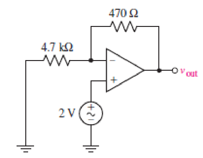
FIGURE 6.63
(a) For the circuit of Fig. 6.63, if the op amp (assume LT1001) is powered by matched 9 V supplies, estimate the maximum value to which the 470 Ω resistor can be increased before saturation effects become apparent. (b) Verify your prediction with an appropriate simulation.
Expert Solution & Answer
Want to see the full answer?
Check out a sample textbook solution
Students have asked these similar questions
*Assume op amps to be ideal
For the signal and circuit of Figure 6, the op-amp has a slew rate of SR=0.75 V/µs.
a) Calculate the maximum frequency that may be used.
b) Determine if the signal will be an amplified duplicate at the output.
Design a simple op-amp circuit which
will---
Sinusoidal wave (2V p-p, 1kHz) to
amplified Square wave converter
maintaining the same frequency
Chapter 6 Solutions
Loose Leaf for Engineering Circuit Analysis Format: Loose-leaf
Ch. 6.2 - Derive an expression for vout in terms of vin for...Ch. 6.2 - Prob. 2PCh. 6.3 - An historic bridge is showing signs of...Ch. 6.4 - Design a circuit that provides a 12 V output if a...Ch. 6.4 - Design a noninverting Schmitt trigger that that...Ch. 6.5 - Assuming a finite open-loop gain (A), a finite...Ch. 6.5 - Use SPICE to simulate a voltage follower using an...Ch. 6 - For the op amp circuit shown in Fig. 6.39,...Ch. 6 - FIGURE 6.39 Determine the power dissipated by a...Ch. 6 - For the circuit of Fig. 6.40, calculate vout if...
Ch. 6 - For the circuit in Fig. 6.40, find the values of...Ch. 6 - (a) Design a circuit which converts a voltage...Ch. 6 - Prob. 6ECh. 6 - For the circuit of Fig. 6.40, R1 = RL = 50 ....Ch. 6 - Prob. 8ECh. 6 - (a) Design a circuit using only a single op amp...Ch. 6 - Prob. 11ECh. 6 - Determine the output voltage v0 and the current...Ch. 6 - Prob. 13ECh. 6 - Prob. 14ECh. 6 - Prob. 15ECh. 6 - Prob. 16ECh. 6 - Consider the amplifier circuit shown in Fig. 6.46....Ch. 6 - Prob. 18ECh. 6 - Prob. 19ECh. 6 - Prob. 20ECh. 6 - Referring to Fig. 6.49, sketch vout as a function...Ch. 6 - Repeat Exercise 21 using a parameter sweep in...Ch. 6 - Obtain an expression for vout as labeled in the...Ch. 6 - Prob. 24ECh. 6 - Prob. 25ECh. 6 - Prob. 26ECh. 6 - Prob. 27ECh. 6 - Prob. 28ECh. 6 - Prob. 29ECh. 6 - Prob. 30ECh. 6 - Prob. 31ECh. 6 - Determine the value of Vout for the circuit in...Ch. 6 - Calculate V0 for the circuit in Fig. 6.55. FIGURE...Ch. 6 - Prob. 34ECh. 6 - The temperature alarm circuit in Fig. 6.56...Ch. 6 - Prob. 36ECh. 6 - For the circuit depicted in Fig. 6.57, sketch the...Ch. 6 - For the circuit depicted in Fig. 6.58, (a) sketch...Ch. 6 - For the circuit depicted in Fig. 6.59, sketch the...Ch. 6 - In digital logic applications, a +5 V signal...Ch. 6 - Using the temperature sensor in the circuit in...Ch. 6 - Examine the comparator Schmitt trigger circuit in...Ch. 6 - Design the circuit values for the single supply...Ch. 6 - For the instrumentation amplifier shown in Fig....Ch. 6 - A common application for instrumentation...Ch. 6 - (a) Employ the parameters listed in Table 6.3 for...Ch. 6 - Prob. 49ECh. 6 - For the circuit of Fig. 6.62, calculate the...Ch. 6 - Prob. 51ECh. 6 - FIGURE 6.63 (a) For the circuit of Fig. 6.63, if...Ch. 6 - The difference amplifier circuit in Fig. 6.32 has...Ch. 6 - Prob. 55ECh. 6 - Prob. 56ECh. 6 - Prob. 57ECh. 6 - Prob. 58ECh. 6 - Prob. 59ECh. 6 - Prob. 60ECh. 6 - A fountain outside a certain office building is...Ch. 6 - For the circuit of Fig. 6.44, let all resistor...
Additional Engineering Textbook Solutions
Find more solutions based on key concepts
Three point charges of equal magnitude q, that will yield a zero net electric field at the origin.
Engineering Electromagnetics
The current source in the circuit shown generates the current pulse
Find (a) v (0); (b) the instant of time gr...
Electric Circuits. (11th Edition)
Explain the main function of each of the following major components of a PLC: a. Processor module (CPU) b. I/O ...
Programmable Logic Controllers
For the “tank” circuit in Fig. 14.79, find the resonant frequency.
Figure 14.79
For Probs. 14.39, 14.71, and 1...
Fundamentals of Electric Circuits
When travelers from the USA and Canada visit Europe, they encounter a different power distribution system. Wall...
Electric machinery fundamentals
How many coulombs do 93.8 1016 electrons represent?
Principles Of Electric Circuits
Knowledge Booster


Learn more about
Need a deep-dive on the concept behind this application? Look no further. Learn more about this topic, electrical-engineering and related others by exploring similar questions and additional content below.Similar questions
- What output voltage results in the circuit below for an input of 0.5 V. Refer to the following for the values of Rf = 413981 ohms, R1 = 16788 ohms. Express your answer up to two decimal places. ... V. 360 kQ 12 ko Round your answer to 2 decimal places.arrow_forwardAssuming an ideal op amp, design and draw the circuits for the following. Your resistor values must be between 1k and 100k, inclusive. (a) An op amp circuit with a gain of -5 V/V (b) An op amp circuit with a gain of 3 V/Varrow_forwardAn op amp has Vsat = +/- 13 V, SR = 1.7 V/μs, and is used as a comparator. What is the approximate time it takes to transition from one output state to the other?arrow_forward
- design and Draw the circuit of op-amp monostable multivibrator with fo= 200KHz and duty cycle of 40%arrow_forwardThe Junction Gate Field Effect Transistor is one of the simplest types of field-effect transistor. It is a three-terminal semiconductor device .One of its function is, it serve as an amplifier. As an Engineer you are to design a single stage JFET Amplifier. Explain in your own words this circuit operates, identifying each component in your design circuit and state their functionsarrow_forwardDesign an inverting op amp circuit with 6.5 gainarrow_forward
- A. Given the comparator circuits (with supply voltages at +15 V) below, draw and label the outputlevels:arrow_forward2K The op amp used in the inverting amplifier circuit is not ideal. In fact, it is an LM741 with the following parameters: v W Rin = 2 MQ, AoL = 200 V/mV, Rout = 200 Q. Determine the gain vo/vi of the op amp circuit. If the gain computed in a is the actual gain, what is the percentage accuracy of the computed gain if the op amp is considered ideal? 4. 1K vo а. b.arrow_forwardDesign an op-amp circuit to have the following output V. = 4 - 3 dt. Maximum file size: 4GB maximum numarrow_forward
- A circuit consist of two cascaded opamp amplifiers, If the gain of first stage is 6.7 and the gain of the second stage is 3. Then the total voltage gain A, isarrow_forwardDesign an op-amp circuit that can perform this operation: 1)V subscript 0 equals negative fraction numerator V subscript 1 over denominator 2 V subscript 2 end fraction . 2)Draw the circuit diagram and show all the calculations as well as your assumptions.arrow_forward1. Calculate the voltage of an inverting op-amp summing amplifier for the following for the following sets of resistors. Use Rf = 1 M ohms in all cases.arrow_forward
arrow_back_ios
SEE MORE QUESTIONS
arrow_forward_ios
Recommended textbooks for you
 Introductory Circuit Analysis (13th Edition)Electrical EngineeringISBN:9780133923605Author:Robert L. BoylestadPublisher:PEARSON
 Delmar's Standard Textbook Of ElectricityElectrical EngineeringISBN:9781337900348Author:Stephen L. HermanPublisher:Cengage Learning
 Programmable Logic ControllersElectrical EngineeringISBN:9780073373843Author:Frank D. PetruzellaPublisher:McGraw-Hill Education
 Fundamentals of Electric CircuitsElectrical EngineeringISBN:9780078028229Author:Charles K Alexander, Matthew SadikuPublisher:McGraw-Hill Education
 Electric Circuits. (11th Edition)Electrical EngineeringISBN:9780134746968Author:James W. Nilsson, Susan RiedelPublisher:PEARSON
 Engineering ElectromagneticsElectrical EngineeringISBN:9780078028151Author:Hayt, William H. (william Hart), Jr, BUCK, John A.Publisher:Mcgraw-hill Education,
Introductory Circuit Analysis (13th Edition)
Electrical Engineering
ISBN:9780133923605
Author:Robert L. Boylestad
Publisher:PEARSON
Delmar's Standard Textbook Of Electricity
Electrical Engineering
ISBN:9781337900348
Author:Stephen L. Herman
Publisher:Cengage Learning
Programmable Logic Controllers
Electrical Engineering
ISBN:9780073373843
Author:Frank D. Petruzella
Publisher:McGraw-Hill Education
Fundamentals of Electric Circuits
Electrical Engineering
ISBN:9780078028229
Author:Charles K Alexander, Matthew Sadiku
Publisher:McGraw-Hill Education
Electric Circuits. (11th Edition)
Electrical Engineering
ISBN:9780134746968
Author:James W. Nilsson, Susan Riedel
Publisher:PEARSON
Engineering Electromagnetics
Electrical Engineering
ISBN:9780078028151
Author:Hayt, William H. (william Hart), Jr, BUCK, John A.
Publisher:Mcgraw-hill Education,
Current Divider Rule; Author: Neso Academy;https://www.youtube.com/watch?v=hRU1mKWUehY;License: Standard YouTube License, CC-BY