
Loose Leaf for Engineering Circuit Analysis Format: Loose-leaf
9th Edition
ISBN: 9781259989452
Author: Hayt
Publisher: Mcgraw Hill Publishers
expand_more
expand_more
format_list_bulleted
Concept explainers
Videos
Textbook Question
Chapter 6, Problem 38E
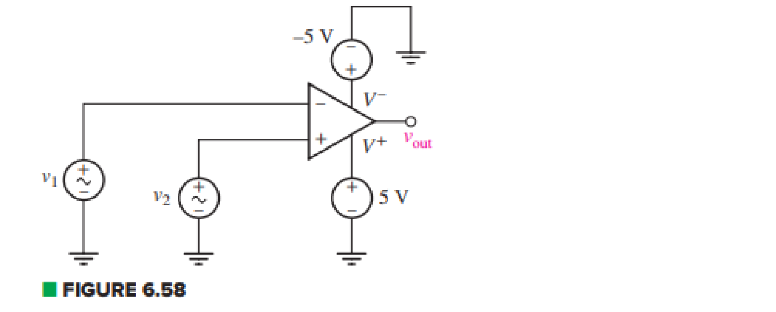
For the circuit depicted in Fig. 6.58, (a) sketch the expected output voltage vout as a function of v1 for –5 V ≤ v1 ≤ +5 V, if v2 = +2 V; (b) sketch the expected output voltage vout as a function of v2 for –5 V ≤ v2 ≤ +5 V, if v1 = +2 V.
Expert Solution & Answer
Want to see the full answer?
Check out a sample textbook solution
Students have asked these similar questions
I. An op amp has a GBP of 106. A 0.3 µV sinusoidal signal at 5 KHz is required to be
amplified to 5 V. Calculate the gains and draw the schematic circuit to achieve this.
A power suppply having 220 V AC input and two fixed outputs as 10 V DC and 20 V DC is requested from you. For this purpose, a transformer with 220 V AC input / 15 V AC output, some capacitors, some silicon diodes, and zener diodes are presented.
a) Design your power supply and point out DC voltage outputs
b) Explain the operation of the network and all the components used in the design
c) Calculate and plot input and output signals of the network
Hint: For design, remember clipper, clamper, rectifier,voltage multiplier and zener circuits
For the inverting amplifier in Fig. 6_3, if Vin=-50 cos10t (V), R₁= 200 Ohm and R-20 Ohm; what is Vout
?
Vin
5 cos10t (V)
- 5 cos10t (V)
R1
ww
Fig. 6_3
-1000 cos10t (V)
O 1000 cos10t (V)
Rf
ww
Vout
Chapter 6 Solutions
Loose Leaf for Engineering Circuit Analysis Format: Loose-leaf
Ch. 6.2 - Derive an expression for vout in terms of vin for...Ch. 6.2 - Prob. 2PCh. 6.3 - An historic bridge is showing signs of...Ch. 6.4 - Design a circuit that provides a 12 V output if a...Ch. 6.4 - Design a noninverting Schmitt trigger that that...Ch. 6.5 - Assuming a finite open-loop gain (A), a finite...Ch. 6.5 - Use SPICE to simulate a voltage follower using an...Ch. 6 - For the op amp circuit shown in Fig. 6.39,...Ch. 6 - FIGURE 6.39 Determine the power dissipated by a...Ch. 6 - For the circuit of Fig. 6.40, calculate vout if...
Ch. 6 - For the circuit in Fig. 6.40, find the values of...Ch. 6 - (a) Design a circuit which converts a voltage...Ch. 6 - Prob. 6ECh. 6 - For the circuit of Fig. 6.40, R1 = RL = 50 ....Ch. 6 - Prob. 8ECh. 6 - (a) Design a circuit using only a single op amp...Ch. 6 - Prob. 11ECh. 6 - Determine the output voltage v0 and the current...Ch. 6 - Prob. 13ECh. 6 - Prob. 14ECh. 6 - Prob. 15ECh. 6 - Prob. 16ECh. 6 - Consider the amplifier circuit shown in Fig. 6.46....Ch. 6 - Prob. 18ECh. 6 - Prob. 19ECh. 6 - Prob. 20ECh. 6 - Referring to Fig. 6.49, sketch vout as a function...Ch. 6 - Repeat Exercise 21 using a parameter sweep in...Ch. 6 - Obtain an expression for vout as labeled in the...Ch. 6 - Prob. 24ECh. 6 - Prob. 25ECh. 6 - Prob. 26ECh. 6 - Prob. 27ECh. 6 - Prob. 28ECh. 6 - Prob. 29ECh. 6 - Prob. 30ECh. 6 - Prob. 31ECh. 6 - Determine the value of Vout for the circuit in...Ch. 6 - Calculate V0 for the circuit in Fig. 6.55. FIGURE...Ch. 6 - Prob. 34ECh. 6 - The temperature alarm circuit in Fig. 6.56...Ch. 6 - Prob. 36ECh. 6 - For the circuit depicted in Fig. 6.57, sketch the...Ch. 6 - For the circuit depicted in Fig. 6.58, (a) sketch...Ch. 6 - For the circuit depicted in Fig. 6.59, sketch the...Ch. 6 - In digital logic applications, a +5 V signal...Ch. 6 - Using the temperature sensor in the circuit in...Ch. 6 - Examine the comparator Schmitt trigger circuit in...Ch. 6 - Design the circuit values for the single supply...Ch. 6 - For the instrumentation amplifier shown in Fig....Ch. 6 - A common application for instrumentation...Ch. 6 - (a) Employ the parameters listed in Table 6.3 for...Ch. 6 - Prob. 49ECh. 6 - For the circuit of Fig. 6.62, calculate the...Ch. 6 - Prob. 51ECh. 6 - FIGURE 6.63 (a) For the circuit of Fig. 6.63, if...Ch. 6 - The difference amplifier circuit in Fig. 6.32 has...Ch. 6 - Prob. 55ECh. 6 - Prob. 56ECh. 6 - Prob. 57ECh. 6 - Prob. 58ECh. 6 - Prob. 59ECh. 6 - Prob. 60ECh. 6 - A fountain outside a certain office building is...Ch. 6 - For the circuit of Fig. 6.44, let all resistor...
Knowledge Booster


Learn more about
Need a deep-dive on the concept behind this application? Look no further. Learn more about this topic, electrical-engineering and related others by exploring similar questions and additional content below.Similar questions
- For the difference amplifier in Fig. 6_4, if V₁ = 3 sin10t (V), V₂ = 6 sin 10t (V), and R= 20 Ohm, what is Vout? V₁ V₂ 3 sin10t (V) -3 sin10t (V) -9 sin10t (V) 9 sin 10t (V) R R www R Fig. 6_4 R ww - Vout RLarrow_forwardA certain solar cell type has an output capability of 9.2 A at 0.7 V. A series / parallel solar array has been designed of such cells with 11 parallel strings and each string has 114 cells in series. Calculate Voltage capability of array.arrow_forwardA certain solar cell type has an output capability of 0.9 A at 0.6 V. A series / parallel solar array has been designed of such cells with 144 parallel strings and each string has 210 cells in series. Calculate Current capability of array.arrow_forward
- 7) The circuit shown below is used to drive an LED with a voltage source. The circuit can also be thought of as a current amplifier in that, with the proper design, ip > i₁. (a) Derive the expression for ip in terms of i₁ and the resistors. (b) Design the circuit such that ip = 12 mA and i₁ = 1 mA for v₁ = 5 V. RE 210 R₁ www + R₂ Mli iD 7 Light OVOarrow_forwardTo increase the 75 V battery voltage to 100 V, a da-da circuit is required is heard. The converter inductance is 200 μH and the load resistance is 2.2 Ω.Powerswitch has a transmission time of 50 μs and operates in continuous transmission. According to this; d) Find the average value of the input current and the output current. e) Find the minimum and maximum values of the input current. f) Output to be used to limit the fluctuation in the input voltage to 10% of the output voltage.Find the capacity of the circuit.arrow_forward5. Design an op-amp Voltmeter circuit which can measure a maximum input of 20 mV The op-amp input current is 0.2 µA, and the meter circuit has Im= 100 µA FSD and Rm=10kQ. Determine suitable resistance values for Ra and Rarrow_forward
- One can assemble a “virtual” solar cell array by using playing cards, or business or index cards, to represent a solar cell. Combinations of these cards in series and/or parallel can model the required array output. Assume each card has an output of 0.5 V and a current (under bright light) of 2 A. Using your cards, how would you arrange them to produce an output of 6 A at 3 V (18 W)?Suppose you were told that you needed only 18 W (but no required voltage). Would you need more cards to make thisarrangement?arrow_forwardAssuming an ideal op amp, design and draw the circuits for the following. Your resistor values must be between 1k and 100k, inclusive. (a) An op amp circuit with a gain of -5 V/V (b) An op amp circuit with a gain of 3 V/Varrow_forward3 In a circuit which needs proper coupling such that DC isolation is attained (i.e DC conditions of the input does not influence the DC conditions of the following circuit) and with no amplification factor which circuit you have studied will serve the purpose. Please keep in mind that the larger circuit is intended to be laid out onto an Integrated Chip. Briefly explain with appropriate diagram the circuit you infer satisfies the requirements stated above. The circuit described above is a linear or nonlinear application of operational amplifier. With one example explain how the above circuit can be used in a larger circuit and how it satisfies the requirements mentioned above. 4 Any normal amplifier cannot be used as an instrumentation amplifier. WHY? List out the basic requirements of an instrumentation amplifier. Explain how you would incorporate these requirements into your instrumentation amplifier.arrow_forward
- Level measurement in a sump tank is provided by a transducer scaled as 1.638 V/m. A pump is to be turned on by application of 7 V when the sump level exceeds 8.5 m. The pump is to be turned back off when the sump level drops to 3.5 m. Find VH and VL .Given R1/R2 = 1.5. a) VH= b) VL=arrow_forwarda) find the voltage in the circuit below. b) specify whether the Op amps used in the circuit are inverted or not.arrow_forward1. Find V, and I, in the cascaded Op Amp circuit given below with two Op Amps: 20mV + www 12K2 www 3KQ Answer: V 350 mA, I = 25 μA b wwwww 10KQ www 4KQarrow_forward
arrow_back_ios
SEE MORE QUESTIONS
arrow_forward_ios
Recommended textbooks for you
 Introductory Circuit Analysis (13th Edition)Electrical EngineeringISBN:9780133923605Author:Robert L. BoylestadPublisher:PEARSON
 Delmar's Standard Textbook Of ElectricityElectrical EngineeringISBN:9781337900348Author:Stephen L. HermanPublisher:Cengage Learning
 Programmable Logic ControllersElectrical EngineeringISBN:9780073373843Author:Frank D. PetruzellaPublisher:McGraw-Hill Education
 Fundamentals of Electric CircuitsElectrical EngineeringISBN:9780078028229Author:Charles K Alexander, Matthew SadikuPublisher:McGraw-Hill Education
 Electric Circuits. (11th Edition)Electrical EngineeringISBN:9780134746968Author:James W. Nilsson, Susan RiedelPublisher:PEARSON
 Engineering ElectromagneticsElectrical EngineeringISBN:9780078028151Author:Hayt, William H. (william Hart), Jr, BUCK, John A.Publisher:Mcgraw-hill Education,
Introductory Circuit Analysis (13th Edition)
Electrical Engineering
ISBN:9780133923605
Author:Robert L. Boylestad
Publisher:PEARSON
Delmar's Standard Textbook Of Electricity
Electrical Engineering
ISBN:9781337900348
Author:Stephen L. Herman
Publisher:Cengage Learning
Programmable Logic Controllers
Electrical Engineering
ISBN:9780073373843
Author:Frank D. Petruzella
Publisher:McGraw-Hill Education
Fundamentals of Electric Circuits
Electrical Engineering
ISBN:9780078028229
Author:Charles K Alexander, Matthew Sadiku
Publisher:McGraw-Hill Education
Electric Circuits. (11th Edition)
Electrical Engineering
ISBN:9780134746968
Author:James W. Nilsson, Susan Riedel
Publisher:PEARSON
Engineering Electromagnetics
Electrical Engineering
ISBN:9780078028151
Author:Hayt, William H. (william Hart), Jr, BUCK, John A.
Publisher:Mcgraw-hill Education,
Current Divider Rule; Author: Neso Academy;https://www.youtube.com/watch?v=hRU1mKWUehY;License: Standard YouTube License, CC-BY