
Loose Leaf for Engineering Circuit Analysis Format: Loose-leaf
9th Edition
ISBN: 9781259989452
Author: Hayt
Publisher: Mcgraw Hill Publishers
expand_more
expand_more
format_list_bulleted
Concept explainers
Videos
Textbook Question
Chapter 6, Problem 64E
For the circuit of Fig. 6.44, let all resistor values equal 5 kΩ. Sketch vout as a function of time if (a) v1 = 5 sin 5t V and v2 = 5 cos 5t V; (b) v1 = 4e−t V and v2 = 5e−2t V; (c) v1 = 2 V and v2 = e−t V.
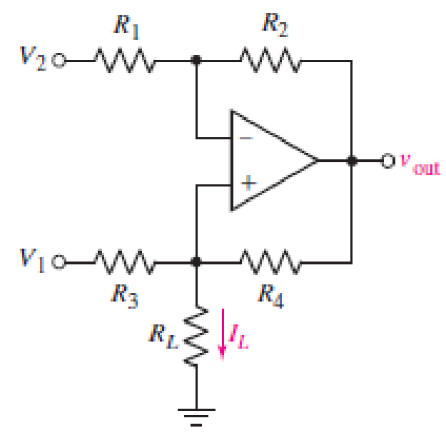
FIGURE 6.64
Expert Solution & Answer
Want to see the full answer?
Check out a sample textbook solution
Students have asked these similar questions
6.51 Determine Leg at terminals a-b of the circuit in
Fig. 6.73.
10 mH
60 mH
25 mH
rell
20 mH
a o
-o b
ell
30 mH
ll
A battery is comprised of 4 cells connected in parallel, each cell has an EMF with 1.5V and an internal resistance of 600.00 mΩ. There is no load connected to the terminal. Solve for Rint.
The R-L Circuit: An inductor with an inductance of 2.50 H and a resistance of 7.00 n is connected to the terminals ofa battery with an emf of 6.00 V and an internal resistance of 1.00 n. What is the rate ofincrease of current at the instant when the current is 0.500 A? A) 0.8 A/s B) 0.6 A/s C) 0.4 A/s D) zero E) None of the above.
Chapter 6 Solutions
Loose Leaf for Engineering Circuit Analysis Format: Loose-leaf
Ch. 6.2 - Derive an expression for vout in terms of vin for...Ch. 6.2 - Prob. 2PCh. 6.3 - An historic bridge is showing signs of...Ch. 6.4 - Design a circuit that provides a 12 V output if a...Ch. 6.4 - Design a noninverting Schmitt trigger that that...Ch. 6.5 - Assuming a finite open-loop gain (A), a finite...Ch. 6.5 - Use SPICE to simulate a voltage follower using an...Ch. 6 - For the op amp circuit shown in Fig. 6.39,...Ch. 6 - FIGURE 6.39 Determine the power dissipated by a...Ch. 6 - For the circuit of Fig. 6.40, calculate vout if...
Ch. 6 - For the circuit in Fig. 6.40, find the values of...Ch. 6 - (a) Design a circuit which converts a voltage...Ch. 6 - Prob. 6ECh. 6 - For the circuit of Fig. 6.40, R1 = RL = 50 ....Ch. 6 - Prob. 8ECh. 6 - (a) Design a circuit using only a single op amp...Ch. 6 - Prob. 11ECh. 6 - Determine the output voltage v0 and the current...Ch. 6 - Prob. 13ECh. 6 - Prob. 14ECh. 6 - Prob. 15ECh. 6 - Prob. 16ECh. 6 - Consider the amplifier circuit shown in Fig. 6.46....Ch. 6 - Prob. 18ECh. 6 - Prob. 19ECh. 6 - Prob. 20ECh. 6 - Referring to Fig. 6.49, sketch vout as a function...Ch. 6 - Repeat Exercise 21 using a parameter sweep in...Ch. 6 - Obtain an expression for vout as labeled in the...Ch. 6 - Prob. 24ECh. 6 - Prob. 25ECh. 6 - Prob. 26ECh. 6 - Prob. 27ECh. 6 - Prob. 28ECh. 6 - Prob. 29ECh. 6 - Prob. 30ECh. 6 - Prob. 31ECh. 6 - Determine the value of Vout for the circuit in...Ch. 6 - Calculate V0 for the circuit in Fig. 6.55. FIGURE...Ch. 6 - Prob. 34ECh. 6 - The temperature alarm circuit in Fig. 6.56...Ch. 6 - Prob. 36ECh. 6 - For the circuit depicted in Fig. 6.57, sketch the...Ch. 6 - For the circuit depicted in Fig. 6.58, (a) sketch...Ch. 6 - For the circuit depicted in Fig. 6.59, sketch the...Ch. 6 - In digital logic applications, a +5 V signal...Ch. 6 - Using the temperature sensor in the circuit in...Ch. 6 - Examine the comparator Schmitt trigger circuit in...Ch. 6 - Design the circuit values for the single supply...Ch. 6 - For the instrumentation amplifier shown in Fig....Ch. 6 - A common application for instrumentation...Ch. 6 - (a) Employ the parameters listed in Table 6.3 for...Ch. 6 - Prob. 49ECh. 6 - For the circuit of Fig. 6.62, calculate the...Ch. 6 - Prob. 51ECh. 6 - FIGURE 6.63 (a) For the circuit of Fig. 6.63, if...Ch. 6 - The difference amplifier circuit in Fig. 6.32 has...Ch. 6 - Prob. 55ECh. 6 - Prob. 56ECh. 6 - Prob. 57ECh. 6 - Prob. 58ECh. 6 - Prob. 59ECh. 6 - Prob. 60ECh. 6 - A fountain outside a certain office building is...Ch. 6 - For the circuit of Fig. 6.44, let all resistor...
Knowledge Booster


Learn more about
Need a deep-dive on the concept behind this application? Look no further. Learn more about this topic, electrical-engineering and related others by exploring similar questions and additional content below.Similar questions
- 5. A series combination of an 18.0 mF capacitor and a resistor are connected to a 125 V battery. After three seconds, the voltage across the capacitor is 49.5 V. (a) What is the resistance of the resistor? (b) If at that three second mark the battery is subsequently removed and the capacitor is allowed to discharge through the resistor then how many excess electrons will remain on the capacitor at the five second mark?arrow_forward7. Calculate the component currents and loop voliages for the circuit shown in Figur- 6.44, along with the values of I7 and Rp. R, 470 N A 100 n R3 510 N R4 1 kn As 1.5 kn FIGURE 6.44 allel Circuitsarrow_forwardExercise The buck dc-dc converter of Fig. 6-3a has the following parameters: V = 50 V D = 0.4 L = 400 µH C = 100 µ.F f= 20 kHz R= 20 N Assuming ideal components, calculate (a) the output voltage V, (b) the maximum and minimum inductor current, and (c) the output voltage ripple.arrow_forward
- What are the expected readings of the following in the figure below (R-7.60 . AV7.00 V) AV 10.0 0 V. 5.00 0 4.50V (a) ideal ammeter (Give your ansver in mA.) (b) ideal voltmeter (Give your answer in volts.) (c) what If? How vould the readings in the ammeter (in mA) and voltmater (in volta) change if the 4,5o v battery was fipped so that its positive terminal was to the right? ideal ammeter ideal voltmeterarrow_forwardAtt = 0, a 6.00 V battery is connected in series with a 120 mH inductor and a total of 25 Q resistance, as shown in the figure. How long (in ms) will it take the current to reach half its maximum possible value? R ellarrow_forward5. When connected to a 12V battery, a 160mH inductor draws 200mA of current. When connected to a 120V, 60HZ source it draws 800mA. Determine the dc resistance, effective resistance and ac resistance of this component.arrow_forward
- A student wants to measure the electrir potential difference across the battery for the circuit below. R, A B C R, Except from point A to point D, where should a student hook up a voltmeter to measure the electric potential difference across the battery?arrow_forwarda resistance of 100k ohms is connected in series with a 100uF capacitor.if the combination is suddenly connected across a 125V DC source, determine the current one second after the switch is closedarrow_forwardWe connect a 6 uF capacitor to the terminals of a 12 V battery, leaving it for a long time. Once the capacitor is fully charged, we remove the 12 V battery. Next, we connect the positive plate of the capacitor to the positive terminal of a 6 V battery, and the negative plate of the capacitor to the battery's negative terminal. At the moment the capacitor is connected to the 6 V battery, draw the new circuit. Indicate which plate of the capacitor is positive/negative and the direction of current flow, Calculate the current in the circuit or explain why you can't if it's not possible. Either way, give some qualitative description of what happens. Hint: where is the resistance in a DC circuit without a resistor?arrow_forward
- Circuit Theory: I have this following circuit but its not producing the correct output. My input is a 0-3.3 V sine wave at 1 kHz. My output at the speaker should also be a 0-3.3 V sine wave, but its giving me the wrong output. How do I fix this circuit using transistor(s) or any other components? How do I actually apply my knowledge of circuits to this real world problem that I'm stuck?arrow_forward(2= 6.3x10 12. the figure shows a simple RC circuit consisting of a 100-V battery in series with a 10-μF capacitor and a resistor. Initially, the switch S is open and the capacitor is uncharged. Two seconds after the switch is closed, the voltage across the resistor is 37 V. How much charge is on the capacitor 2.0 s after Ve=V₂ (1-e / RC) 6-3 = 1010 (1-c = ²2²) the switch is closed? -2x10⁵ a. 1.1 x 10-³ C b. 2.9 x 10⁻³ C C. 3.7 x 10⁻⁴ C d. 6.3 x 10⁻⁴C e. a. 63 = 1- e b. b. C. 1-e-R 5.2 x 10-4 Chex100 = 1n 37 R -20 -2x10⁵ R =-.994 100 V Causes it to rotate about an axis prallel to the Z-axis. is zero Causes it to rotate about an axis prallel to the x-axis. d. none of these. e Causes it to rotate about an axis prallel to the y-axis. 374 R R=2011 56.1908 The figure shows a rectangular coil carrying a steady current (1). There is a separate, external magnetic field pointing toward the right and parallel to the x-axis. Notice that thet he z-axis is out of the page. The torque on the coil:…arrow_forward6.51 Determine Leg at terminals a-b of the circuit in Fig. 6.73. 10 mH elll 60 mH 25 mH 20 mH all b ell 30 mH ll Figure 6.73arrow_forward
arrow_back_ios
SEE MORE QUESTIONS
arrow_forward_ios
Recommended textbooks for you
 Introductory Circuit Analysis (13th Edition)Electrical EngineeringISBN:9780133923605Author:Robert L. BoylestadPublisher:PEARSON
 Delmar's Standard Textbook Of ElectricityElectrical EngineeringISBN:9781337900348Author:Stephen L. HermanPublisher:Cengage Learning
 Programmable Logic ControllersElectrical EngineeringISBN:9780073373843Author:Frank D. PetruzellaPublisher:McGraw-Hill Education
 Fundamentals of Electric CircuitsElectrical EngineeringISBN:9780078028229Author:Charles K Alexander, Matthew SadikuPublisher:McGraw-Hill Education
 Electric Circuits. (11th Edition)Electrical EngineeringISBN:9780134746968Author:James W. Nilsson, Susan RiedelPublisher:PEARSON
 Engineering ElectromagneticsElectrical EngineeringISBN:9780078028151Author:Hayt, William H. (william Hart), Jr, BUCK, John A.Publisher:Mcgraw-hill Education,
Introductory Circuit Analysis (13th Edition)
Electrical Engineering
ISBN:9780133923605
Author:Robert L. Boylestad
Publisher:PEARSON
Delmar's Standard Textbook Of Electricity
Electrical Engineering
ISBN:9781337900348
Author:Stephen L. Herman
Publisher:Cengage Learning
Programmable Logic Controllers
Electrical Engineering
ISBN:9780073373843
Author:Frank D. Petruzella
Publisher:McGraw-Hill Education
Fundamentals of Electric Circuits
Electrical Engineering
ISBN:9780078028229
Author:Charles K Alexander, Matthew Sadiku
Publisher:McGraw-Hill Education
Electric Circuits. (11th Edition)
Electrical Engineering
ISBN:9780134746968
Author:James W. Nilsson, Susan Riedel
Publisher:PEARSON
Engineering Electromagnetics
Electrical Engineering
ISBN:9780078028151
Author:Hayt, William H. (william Hart), Jr, BUCK, John A.
Publisher:Mcgraw-hill Education,
Capacitors Explained - The basics how capacitors work working principle; Author: The Engineering Mindset;https://www.youtube.com/watch?v=X4EUwTwZ110;License: Standard YouTube License, CC-BY