
Loose Leaf for Engineering Circuit Analysis Format: Loose-leaf
9th Edition
ISBN: 9781259989452
Author: Hayt
Publisher: Mcgraw Hill Publishers
expand_more
expand_more
format_list_bulleted
Concept explainers
Videos
Textbook Question
Chapter 8, Problem 11E
For the circuit in Fig. 8.56, find (a) the total energy stored in the capacitor before the switch is opened, (b) find an expression for the energy stored in the capacitor and power supplied by the capacitor for t > 0, and (c) plot the resulting expressions for w(t) and p(t) using an appropriate range of time.
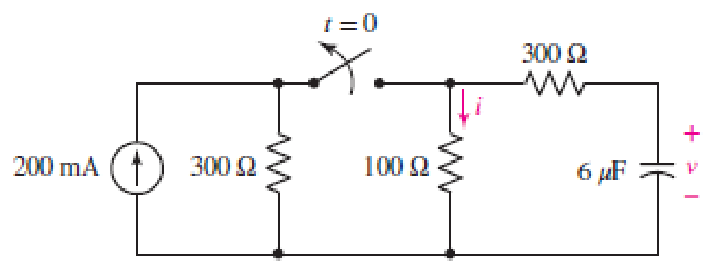
■ FIGURE 8.56
Expert Solution & Answer
Want to see the full answer?
Check out a sample textbook solution
Students have asked these similar questions
A series circuit has a capacitor of 1.5625x10^(-8)F a resistor of 2x10^4 ohms, and an inductor of 1H. If the initial charge on the capacitor is zero,. if a 12-volt battery is connected to the circuit and the circuit is closed at t=0, determine the charge on the capacitor at any time t
A capacitor sensor consists of 3 charged parallel plates have breath of 500 mm. These plates are separated from each other by 7.5 mm. When, the middle plate is moving up by 0.25 mm. Assuming upper and lower plates kept fixed, calculate the following,
i. Length of the capacitor plates, if the total change in capacitance is 1.190 pF
ii. Values of C1 and C2.
GROUP 8
LRC series circuit connected in series with resistance of 4 ohms,
a capacitor of 26 farad and an inductance of ½ henry has an
applied voltage E(t) = 16 cos 2t. There is no initial current and no
initial charge on the capacitor'
a) Find the expression for the current I(t) flowing through the
circuit at any
time t
b) If the applied voltage is removed, what will happen to the
current flow after a long time?
c) If the applied voltage is charged to E(t)-16 cos 6t, what will
happen to the current flow?
Chapter 8 Solutions
Loose Leaf for Engineering Circuit Analysis Format: Loose-leaf
Ch. 8.1 - For the circuit in Fig. 8.2, what value of...Ch. 8.1 - Noting carefully how the circuit changes once the...Ch. 8.2 - In a source-free series RC circuit, find the...Ch. 8.3 - Prob. 4PCh. 8.3 - Prob. 5PCh. 8.4 - Prob. 6PCh. 8.4 - Prob. 7PCh. 8.4 - Prob. 8PCh. 8.5 - Evaluate each of the following at t = 0.8: (a)...Ch. 8.6 - For the circuit of Fig. 8.37, find vc(t) at t...
Ch. 8.7 - Prob. 11PCh. 8.7 - The voltage source 60 40u(t) V is in series with...Ch. 8.7 - Prob. 13PCh. 8.8 - Prob. 14PCh. 8.8 - Prob. 15PCh. 8 - A source-free RC circuit has R = 4 k and C = 22 F,...Ch. 8 - A source-free RC circuit has v(0) = 12 V and R =...Ch. 8 - The resistor in the circuit of Fig. 8.51 has been...Ch. 8 - Prob. 4ECh. 8 - Prob. 5ECh. 8 - Prob. 6ECh. 8 - Prob. 7ECh. 8 - Prob. 8ECh. 8 - Prob. 9ECh. 8 - The switch in Fig. 8.56 has been closed for a long...Ch. 8 - For the circuit in Fig. 8.56, find (a) the total...Ch. 8 - Design a capacitor-based circuit that can achieve...Ch. 8 - (a) Graph the function f (t) = 10e2t over the...Ch. 8 - The current i(t) flowing through a 1 k resistor is...Ch. 8 - Radiocarbon dating has a similar exponential time...Ch. 8 - For the circuit of Fig. 8.4, compute the time...Ch. 8 - Design a circuit which will produce a current of 1...Ch. 8 - Prob. 18ECh. 8 - Prob. 19ECh. 8 - Referring to the circuit shown in Fig. 8.11,...Ch. 8 - Prob. 21ECh. 8 - With the assumption that the switch in the circuit...Ch. 8 - The switch in Fig. 8.57 has been closed since...Ch. 8 - The switch in the circuit of Fig. 8.58 has been...Ch. 8 - Assuming the switch initially has been open for a...Ch. 8 - (a) Obtain an expression for v(t), the voltage...Ch. 8 - For the circuit of Fig. 8.61, determine ix, iL,...Ch. 8 - Prob. 28ECh. 8 - Prob. 29ECh. 8 - Prob. 30ECh. 8 - Prob. 31ECh. 8 - (a) Obtain an expression for vx as labeled in the...Ch. 8 - Prob. 33ECh. 8 - Prob. 34ECh. 8 - Prob. 35ECh. 8 - Prob. 36ECh. 8 - Prob. 37ECh. 8 - The switch in Fig. 8.70 is moved from A to B at t...Ch. 8 - Prob. 39ECh. 8 - Prob. 40ECh. 8 - Evaluate the following functions at t = 1, 0, and...Ch. 8 - Prob. 42ECh. 8 - Prob. 43ECh. 8 - Prob. 44ECh. 8 - You can use MATLAB to represent the unit-step...Ch. 8 - With reference to the circuit depicted in Fig....Ch. 8 - For the circuit given in Fig. 8.75, (a) determine...Ch. 8 - Prob. 48ECh. 8 - Prob. 49ECh. 8 - You build a portable solar charging circuit...Ch. 8 - The switch in the circuit of Fig. 8.78 has been...Ch. 8 - The switch in the circuit of Fig. 8.78 has been...Ch. 8 - Prob. 53ECh. 8 - Prob. 54ECh. 8 - Prob. 55ECh. 8 - For the circuit represented in Fig. 8.82, (a)...Ch. 8 - Prob. 58ECh. 8 - Prob. 59ECh. 8 - For the circuit given in Fig. 8.85, (a) determine...Ch. 8 - The circuit depicted in Fig. 8.86 contains two...Ch. 8 - Prob. 62ECh. 8 - Prob. 63ECh. 8 - A series RL circuit has a voltage that steps from...Ch. 8 - For the two-source circuit of Fig. 8.89, note that...Ch. 8 - (a) Obtain an expression for iL as labeled in Fig....Ch. 8 - Obtain an expression for i(t) as labeled in the...Ch. 8 - Obtain an expression for i1 as indicated in Fig....Ch. 8 - Plot the current i(t) in Fig. 8.93 if (a) R = 10 ;...Ch. 8 - A dc motor can be modeled as a series RL circuit...Ch. 8 - Prob. 71ECh. 8 - Prob. 72ECh. 8 - A series RC sequentially switched circuit has R =...Ch. 8 - Refer to the circuit of Fig. 8.95, which contains...Ch. 8 - In the circuit of Fig. 8.95, a 3 mF capacitor is...Ch. 8 - Prob. 78E
Knowledge Booster


Learn more about
Need a deep-dive on the concept behind this application? Look no further. Learn more about this topic, electrical-engineering and related others by exploring similar questions and additional content below.Similar questions
- 3. A ceramic capacitor has an effective plate area of 5cm2 separated by 0.1mm of ceramic of relative permittivity of 100. Calculate the capacitance in microfarads. If the capacitor is given a charge of 1.5 µC what will be the potential difference (pd) between plates? & calculate the energy stored in itarrow_forwardThe figure below shows a capacitor, with capacitance C = 6.47 µF, and a resistor, with resistance R = 5.73 MQ, connected in series to a battery, with = 29.0 V. The circuit has a switch, which is initially open. C 8 + @ (a) What is the circuit's time constant (in seconds)? μC (b) What the maximum charge (in µC) on the capacitor after the switch is closed? (c) What is the current (in µA) through the resistor 10.0 s after the switch s closed? HAarrow_forward(b) A medical technology company is designing a new portable defibrillator for reviving patients whose heart has stopped. The capacitor in the device will be charged to 2000 V and is required to deliver 400 J of energy on discharge. i) Calculate the capacitance required for this capacitor ii) The conducting plates of the capacitor must have an area of 5 m² and be separated by an insulator with thickness of 0.05 mm. Determine the value of dielectric constant for the insulator between the capacitor parallel plates to deliver the intended energy to the patientarrow_forward
- A 220 microfarad capacitor has an initial charged of 800 microcoulomb. It is discharged through a 100-Ω resistor. How long will it take in order for a capacitor to discharge to 100 microcoulomb? 150 microcoulomb? 200 microcoulomb? Make a graphical representation of equivalent charge vs time t, then interpret the grapharrow_forwardQ1 (True/False): A) The current through the capacitor is inversely proportional to the derivative of the voltage across it: Is it true or false? B) In a typical electronic circuit the capacitor blocks DC and couplest he AC to the next stage of the circuit: Is it true or false? C) The more the value of the stray capacitance , the better it is: Is it true or false?arrow_forwardA series RC circuit is not switched on and the initial state charge of capacitance Ugo = 20 V. In the circuit voltage source E= 50 V DC. Resistance R = 6 Q and capacitance C= 100 µF. E dr R Give the answers to two decimal places. a) Give time constant Tau of circuit m8 b) Calculate current after the switch k is closed at the moment t = 0.72 ms. A c) Calculate current after the switch k is closed at the moment t= 2*Tau.arrow_forward
- 4. The current through a 1 µF capacitor is shown below. At t = 0, the voltage is zero. Sketch the voltage, power, and stored energy to scale versus time. + v(t) o i(t) (a) C= 1 μF i(t) (mA) 20 -20- 2 3 (b) t (ms)arrow_forward1) Determine the Capacitance value to calculate the time constant of the circuit.2) Determine the time constant of the circuit for the capacities you have determined.3) For the capacity value, calculate the estimated time to come to the final state.4) Plot capacitor current and voltage graphs and show if it works in harmony with the time constant you calculated.NOTE: if you want you can use falstad online circuit simulator.arrow_forwardThe capacitor is sufficiently discharged in the next circuit and the switch is closed at t=0. Answer the question. a) Capacitor current at t=0 and IR(current) b) t=infinity Find the capacitor current and voltage. c) After opening the switch, find the IR, IC. d) Time constant.arrow_forward
- 3. We have seen that in a series RLC circuit, Kirchoff's voltage law (VR +VL + Vc = Vs, where Vs is the supply voltage) leads to a 2nd order differential equation for the current I(t). Let us now consider a parallel RLC circuit consisting of a 5 H inductor, a 10 F capacitor, and a 0.5 N resistor. At time t = 0 s, there is a supply current Is of 5 A. The supply voltage Vs is common to all three components. Kirchoff's current law states that IR + IL + Iç = Is.arrow_forwardIn the figure below, after sitting for a long time in position a, the switch in the circuit was moved to position b att= 0. A student measured and plotted the current (i) flowing through the inductor (graph below) after the switch was moved. The data point on the graph is equal to 8.05A, which occurs at 5 milliseconds. What is the value for X, in milliseconds (the time at which the current is equal to 8.05A) ? a) What is the value of the current source Ix, in Amps? Enter only the numerical value. b) What is the value of the current source Iy, in Amps? Enter only the numerical value. c) What is the time constant, in milliseconds? Enter only the numerical value. d) What is the value of Ra, in Ohms? b Ra t = 0 500mH 10 7 6. 1 X time (ms) Inductor Current (A)arrow_forward7 Use Kirchhoff's loop rule to R2 write two equations describing this cir- cuit (assuming the switch is closed). You may use any of the symbols in the fig- ure and any currents or capacitor charges that you define. opyright C1 C2arrow_forward
arrow_back_ios
SEE MORE QUESTIONS
arrow_forward_ios
Recommended textbooks for you
 Introductory Circuit Analysis (13th Edition)Electrical EngineeringISBN:9780133923605Author:Robert L. BoylestadPublisher:PEARSON
 Delmar's Standard Textbook Of ElectricityElectrical EngineeringISBN:9781337900348Author:Stephen L. HermanPublisher:Cengage Learning
 Programmable Logic ControllersElectrical EngineeringISBN:9780073373843Author:Frank D. PetruzellaPublisher:McGraw-Hill Education
 Fundamentals of Electric CircuitsElectrical EngineeringISBN:9780078028229Author:Charles K Alexander, Matthew SadikuPublisher:McGraw-Hill Education
 Electric Circuits. (11th Edition)Electrical EngineeringISBN:9780134746968Author:James W. Nilsson, Susan RiedelPublisher:PEARSON
 Engineering ElectromagneticsElectrical EngineeringISBN:9780078028151Author:Hayt, William H. (william Hart), Jr, BUCK, John A.Publisher:Mcgraw-hill Education,
Introductory Circuit Analysis (13th Edition)
Electrical Engineering
ISBN:9780133923605
Author:Robert L. Boylestad
Publisher:PEARSON
Delmar's Standard Textbook Of Electricity
Electrical Engineering
ISBN:9781337900348
Author:Stephen L. Herman
Publisher:Cengage Learning
Programmable Logic Controllers
Electrical Engineering
ISBN:9780073373843
Author:Frank D. Petruzella
Publisher:McGraw-Hill Education
Fundamentals of Electric Circuits
Electrical Engineering
ISBN:9780078028229
Author:Charles K Alexander, Matthew Sadiku
Publisher:McGraw-Hill Education
Electric Circuits. (11th Edition)
Electrical Engineering
ISBN:9780134746968
Author:James W. Nilsson, Susan Riedel
Publisher:PEARSON
Engineering Electromagnetics
Electrical Engineering
ISBN:9780078028151
Author:Hayt, William H. (william Hart), Jr, BUCK, John A.
Publisher:Mcgraw-hill Education,
ENA 9.2(1)(En)(Alex) Sinusoids & Phasors - Explanation with Example 9.1 ,9.2 & PP 9.2; Author: Electrical Engineering Academy;https://www.youtube.com/watch?v=vX_LLNl-ZpU;License: Standard YouTube License, CC-BY
Electrical Engineering: Ch 10 Alternating Voltages & Phasors (8 of 82) What is a Phasor?; Author: Michel van Biezen;https://www.youtube.com/watch?v=2I1tF3ixNg0;License: Standard Youtube License