
Loose Leaf for Engineering Circuit Analysis Format: Loose-leaf
9th Edition
ISBN: 9781259989452
Author: Hayt
Publisher: Mcgraw Hill Publishers
expand_more
expand_more
format_list_bulleted
Concept explainers
Videos
Textbook Question
Chapter 8, Problem 22E
With the assumption that the switch in the circuit of Fig. 8.57 has been closed a long, long, long time, calculate iL(t) at (a) the instant just before the switch opens; (b) the instant just after the switch opens; (c) t = 15.8 μs; (d) t = 31.5 μs; (e) t = 78.8 μs.
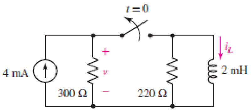
■ FIGURE 8.57
Expert Solution & Answer
Want to see the full answer?
Check out a sample textbook solution
Students have asked these similar questions
8.2 From the circuit in the figure, if the switch is closed for a long time and opens at time ? = 0. Find ?(?) when ? > 0
8.3.3 For the RLC circuit shown in the image below, if R1 = 7 2 and R2 = 7 2, C =
0.36 F, and the power source Vs = 18 V, determine the initial value VR (0T).
%3D
Please pay attention: the numbers may change since they are randomized. Your
answer must include 2 places after the decimal point, and proper SI unit.
R2
Vc
+
VR
R1
2u(t) A
Vs
Your Answer:
Answer
units
118
ll
• AUIB
+
14
Arial
نص عادي
100%
...
31
11· 2I 3 I4I5 6.I 7.I8 I9 110:I 11 I 12 I 13 I 14 I 15 1
The circuit in Fig. 8.12 has reached steady state at t = 0. If the make-
before-break switch moves to position b at t = 0, calculate i(f) for
t> 0.
17 1 18
F
10 Ω
a
ww
t=0
50 V
52
1H
Figure 8.12
For Practice Prob. 8.4.
Answer: e'(5 cos 1.6583t – 7.5378 sin 1.6583f) A.
AR
02:22
acer
ASPIRE ONE
F1
F2
F3
F4
F5
F6
F7
z'
F8
F9
F10
F11
F12
PrtSc
Pause
Break
NumLk
Scr Lk
SysRq
$
&
7
8
8.
5
O 6
9
ww
%23
12 1 11: 10.
8
6
Chapter 8 Solutions
Loose Leaf for Engineering Circuit Analysis Format: Loose-leaf
Ch. 8.1 - For the circuit in Fig. 8.2, what value of...Ch. 8.1 - Noting carefully how the circuit changes once the...Ch. 8.2 - In a source-free series RC circuit, find the...Ch. 8.3 - Prob. 4PCh. 8.3 - Prob. 5PCh. 8.4 - Prob. 6PCh. 8.4 - Prob. 7PCh. 8.4 - Prob. 8PCh. 8.5 - Evaluate each of the following at t = 0.8: (a)...Ch. 8.6 - For the circuit of Fig. 8.37, find vc(t) at t...
Ch. 8.7 - Prob. 11PCh. 8.7 - The voltage source 60 40u(t) V is in series with...Ch. 8.7 - Prob. 13PCh. 8.8 - Prob. 14PCh. 8.8 - Prob. 15PCh. 8 - A source-free RC circuit has R = 4 k and C = 22 F,...Ch. 8 - A source-free RC circuit has v(0) = 12 V and R =...Ch. 8 - The resistor in the circuit of Fig. 8.51 has been...Ch. 8 - Prob. 4ECh. 8 - Prob. 5ECh. 8 - Prob. 6ECh. 8 - Prob. 7ECh. 8 - Prob. 8ECh. 8 - Prob. 9ECh. 8 - The switch in Fig. 8.56 has been closed for a long...Ch. 8 - For the circuit in Fig. 8.56, find (a) the total...Ch. 8 - Design a capacitor-based circuit that can achieve...Ch. 8 - (a) Graph the function f (t) = 10e2t over the...Ch. 8 - The current i(t) flowing through a 1 k resistor is...Ch. 8 - Radiocarbon dating has a similar exponential time...Ch. 8 - For the circuit of Fig. 8.4, compute the time...Ch. 8 - Design a circuit which will produce a current of 1...Ch. 8 - Prob. 18ECh. 8 - Prob. 19ECh. 8 - Referring to the circuit shown in Fig. 8.11,...Ch. 8 - Prob. 21ECh. 8 - With the assumption that the switch in the circuit...Ch. 8 - The switch in Fig. 8.57 has been closed since...Ch. 8 - The switch in the circuit of Fig. 8.58 has been...Ch. 8 - Assuming the switch initially has been open for a...Ch. 8 - (a) Obtain an expression for v(t), the voltage...Ch. 8 - For the circuit of Fig. 8.61, determine ix, iL,...Ch. 8 - Prob. 28ECh. 8 - Prob. 29ECh. 8 - Prob. 30ECh. 8 - Prob. 31ECh. 8 - (a) Obtain an expression for vx as labeled in the...Ch. 8 - Prob. 33ECh. 8 - Prob. 34ECh. 8 - Prob. 35ECh. 8 - Prob. 36ECh. 8 - Prob. 37ECh. 8 - The switch in Fig. 8.70 is moved from A to B at t...Ch. 8 - Prob. 39ECh. 8 - Prob. 40ECh. 8 - Evaluate the following functions at t = 1, 0, and...Ch. 8 - Prob. 42ECh. 8 - Prob. 43ECh. 8 - Prob. 44ECh. 8 - You can use MATLAB to represent the unit-step...Ch. 8 - With reference to the circuit depicted in Fig....Ch. 8 - For the circuit given in Fig. 8.75, (a) determine...Ch. 8 - Prob. 48ECh. 8 - Prob. 49ECh. 8 - You build a portable solar charging circuit...Ch. 8 - The switch in the circuit of Fig. 8.78 has been...Ch. 8 - The switch in the circuit of Fig. 8.78 has been...Ch. 8 - Prob. 53ECh. 8 - Prob. 54ECh. 8 - Prob. 55ECh. 8 - For the circuit represented in Fig. 8.82, (a)...Ch. 8 - Prob. 58ECh. 8 - Prob. 59ECh. 8 - For the circuit given in Fig. 8.85, (a) determine...Ch. 8 - The circuit depicted in Fig. 8.86 contains two...Ch. 8 - Prob. 62ECh. 8 - Prob. 63ECh. 8 - A series RL circuit has a voltage that steps from...Ch. 8 - For the two-source circuit of Fig. 8.89, note that...Ch. 8 - (a) Obtain an expression for iL as labeled in Fig....Ch. 8 - Obtain an expression for i(t) as labeled in the...Ch. 8 - Obtain an expression for i1 as indicated in Fig....Ch. 8 - Plot the current i(t) in Fig. 8.93 if (a) R = 10 ;...Ch. 8 - A dc motor can be modeled as a series RL circuit...Ch. 8 - Prob. 71ECh. 8 - Prob. 72ECh. 8 - A series RC sequentially switched circuit has R =...Ch. 8 - Refer to the circuit of Fig. 8.95, which contains...Ch. 8 - In the circuit of Fig. 8.95, a 3 mF capacitor is...Ch. 8 - Prob. 78E
Knowledge Booster


Learn more about
Need a deep-dive on the concept behind this application? Look no further. Learn more about this topic, electrical-engineering and related others by exploring similar questions and additional content below.Similar questions
- 8. 7.8 In the circuit the voltage and current expressions are v=400e−5tV, t≥0+;i=10e−5tA, t≥0. 5. e) the time (in milliseconds) it takes to dissipate 80% of the initialstored energy.arrow_forward1H + e'u(t) + VR(t) 1F Figure 6.a 6. b) Find the Laplace transformation of the signals shown in Figure 6.b. x(t) 1 ↑ x2(t) 1 2 1 t 4 5, Figure 6.b 7. a) Find the transfer function for the system in Figure 7.a. Sketch pole-zero diagram. Is the system stable? 1 s + 3 s + 2 x(t) y(t) s(s + 3) 2 Figure 7.a b) Find f(t) using inverse Laplace transformation. Sketch the ROC. (8s +10)e -S F(s) = ; -2< Re(s) <-1 (s +1)(s +2) 8. a) Draw the f-i analogous electrical network of the mechanical system shown in Figure 8.a. Page 3 of 7 + +. +arrow_forwardQ8. Assume the switch has been opened for a long time. The switch is closed at t = 0 s. (a) Find the equation of vo(t) for t > 0 s. (b) Plot vo(t) as a function of time starting from t < 0 s. 13 V 6Ω www t = 0 to 3Ω 4 V 5Ω M 4 mF + vo(t)arrow_forward
- Homework 02: a) Write the mathematical expressions for vc, vR1, and ic after the switch is thrown into position 1. b) Find the values of vc, Vr1, and ic when the switch is moved to position 2 at t = 50 ms. c) Write the mathematical expressions for vc, VR2, and ic after the switch is moved to position 3 at t = 80 ms. a) Plot the waveforms of vc and ic for the time period extending from 0 to 300 ms. + vc - C R1 3 ΚΩ ic 10μF 2 3 30 V R2 4 kNarrow_forward8.3.2 For the RLC circuit shown in the image below, if R1 = 1 2 and R2 = 10 S2, C= 0.38 F, and the power source Vs = 19 V, determine the initial value Vc (0"). Please pay attention: the numbers may change since they are randomized. Your answer must include 2 places after the decimal point, and proper SI unit. R2 + VR R1 2u(t) A Vs Your Answer: Answer units エ llarrow_forward8. 7.8 In the circuit , the voltage and current expressions are v=400e−5tV, t≥0+;i=10e−5tA, t≥0.1. a) Rarrow_forward
- 2. Consider the following electrical system: R L C= Uc The equations describing the system dynamics are the following: di(t) u(t) = Lº +(R, +R, )i(t)+u̟(t) dt c du (t) = i(t) dt Choose as state variables: x, (t) = u.(t) and x, (t) = i(t). Obtain the following state space model 1 - C + 1 u R, + R, |X2 L 1 L y =[1 0] + Ou and calculate the system matrices for L = 0.5, R1 = 1, R2 = 1and C = 1. From the state space model obtain the transfer function of the system. By using controllability gramian, check if the system representation R(A,B,C) is controllable. Design a state feedback u(t) = -Kx(t), which will place the closed-loop poles on desired locations: 14 = -1 and 14 = -2. By using observability matrix, check if the system representation R(A, B,C) is observable. Design a reduced-order state observer with desired poles 2d = -2.arrow_forwardQuestion 8. 12V in R₁ A R₁ 5 V C R₂2 w R₂ 4 Consider the circuit below, where the capacitor is uncharged, and the switch is open. The different elements of the circuit have the following values: R₁ = 22, R₂ = 22, R3 = 422, R₁ = 82, R₁ = 82 and C = 10 µF. What is the current I₁ in the circuit when the switch is moved to position 1? Enter your answer, in Amps, in the box below. The answer is acceptable within a tolerance of 0.1 A. h₁: R3 After a long time that the switch has been closed, what is the voltage Vc across the capacitor? Enter your answer, in Volts, in the box below. The answer is acceptable within a tolerance of 0.1 V. Vc:arrow_forwardThe switch in the circuit in Fig. below has been open for a long time. At t=0 the switch is closed. The capacitor voltage (V. (t = 0) )is: 1.8 kN 1 =0 120 V 10 µF 12 kN { 68 k2arrow_forward
- 6. The switches have all been in their starting positions for a long time before moving at the times indicated. Determine and plot ve(t), ic(t), and the energy stored in the capacitor wc(t). (The time scale for your plots should be 0 < t < 36 ms.) 300 mA t = 24ms ਇਸ www 1k 100 mA 2kn t = 12ms 4k0 www 4µF (1) V.(1) 25 mA t=0ms X 4k02 www 200Varrow_forward8002 80V t=0 3F 0.5i(t) 30Ω www 5002 vi(t) The switch in the circuit has been closed for a long time. At t=0 the switch opens. a) Determine the voltage across the capacitor at t-0 b) For t>0, determine the resistance seen at the terminals of the capacitor and the time constant of the circuit. c) Determine i(t) for t>0.arrow_forwardExample A series AC circuit is shown in Fig. 8. Calculate the source current, apparent, real and reactive powers. The expression of the alternating voltage source is v(t) = 16 sin(10t+25°) V. %3D i(1) 42 (1)A 0.9H Figure 8.arrow_forward
arrow_back_ios
SEE MORE QUESTIONS
arrow_forward_ios
Recommended textbooks for you
 Introductory Circuit Analysis (13th Edition)Electrical EngineeringISBN:9780133923605Author:Robert L. BoylestadPublisher:PEARSON
 Delmar's Standard Textbook Of ElectricityElectrical EngineeringISBN:9781337900348Author:Stephen L. HermanPublisher:Cengage Learning
 Programmable Logic ControllersElectrical EngineeringISBN:9780073373843Author:Frank D. PetruzellaPublisher:McGraw-Hill Education
 Fundamentals of Electric CircuitsElectrical EngineeringISBN:9780078028229Author:Charles K Alexander, Matthew SadikuPublisher:McGraw-Hill Education
 Electric Circuits. (11th Edition)Electrical EngineeringISBN:9780134746968Author:James W. Nilsson, Susan RiedelPublisher:PEARSON
 Engineering ElectromagneticsElectrical EngineeringISBN:9780078028151Author:Hayt, William H. (william Hart), Jr, BUCK, John A.Publisher:Mcgraw-hill Education,
Introductory Circuit Analysis (13th Edition)
Electrical Engineering
ISBN:9780133923605
Author:Robert L. Boylestad
Publisher:PEARSON
Delmar's Standard Textbook Of Electricity
Electrical Engineering
ISBN:9781337900348
Author:Stephen L. Herman
Publisher:Cengage Learning
Programmable Logic Controllers
Electrical Engineering
ISBN:9780073373843
Author:Frank D. Petruzella
Publisher:McGraw-Hill Education
Fundamentals of Electric Circuits
Electrical Engineering
ISBN:9780078028229
Author:Charles K Alexander, Matthew Sadiku
Publisher:McGraw-Hill Education
Electric Circuits. (11th Edition)
Electrical Engineering
ISBN:9780134746968
Author:James W. Nilsson, Susan Riedel
Publisher:PEARSON
Engineering Electromagnetics
Electrical Engineering
ISBN:9780078028151
Author:Hayt, William H. (william Hart), Jr, BUCK, John A.
Publisher:Mcgraw-hill Education,
ENA 9.2(1)(En)(Alex) Sinusoids & Phasors - Explanation with Example 9.1 ,9.2 & PP 9.2; Author: Electrical Engineering Academy;https://www.youtube.com/watch?v=vX_LLNl-ZpU;License: Standard YouTube License, CC-BY
Electrical Engineering: Ch 10 Alternating Voltages & Phasors (8 of 82) What is a Phasor?; Author: Michel van Biezen;https://www.youtube.com/watch?v=2I1tF3ixNg0;License: Standard Youtube License