
Loose Leaf for Engineering Circuit Analysis Format: Loose-leaf
9th Edition
ISBN: 9781259989452
Author: Hayt
Publisher: Mcgraw Hill Publishers
expand_more
expand_more
format_list_bulleted
Concept explainers
Videos
Textbook Question
Chapter 8, Problem 3E
The resistor in the circuit of Fig. 8.51 has been included to model the dielectric layer separating the plates of the 3.1 nF capacitor, and it has a value of 55 MΩ. The capacitor is storing 200 mJ of energy just prior to t = 0. (a) Write an expression for v(t) valid for t ≥ 0. (b) Compute the energy remaining in the capacitor at t = 170 ms. (c) Graph v(t) over the range of 0 < t < 850 ms. And identify the value of v(t) when t = 2τ.
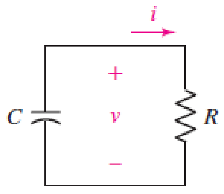
FIGURE 8.51
Expert Solution & Answer
Want to see the full answer?
Check out a sample textbook solution
Students have asked these similar questions
The voltage across a 2µF capacitor is shown. Determine the waveformfor the capacitor current
(a) Find mathematical expression of v(t) for 0 ≤ t ≤ 2
(b) Find mathematical expression of v(t) for 2 ≤ t ≤ 6
(c) Draw the waveform for the capacitor current.
Please see the question and figure in the image: The initial voltage on the 0.5 mF capacitor shown below is −20V at t = 0. The capacitor current is ic(t) = 0.070e−1000t A. a) How much energy is stored in the capacitor at t = 500ms? b) How much energy is stored in the capacitor as time goes to infinity?
8. A series RC circuit (Fig. 1 below) with one resistor (R=500 M) and one capacitor
(C=0.5 µF) is connected to an AC voltage supply which supplies a voltage v=100
sin(1000t+309) (from t=0 to t=∞). The initial charge on the capacitor is Qo = 25 µC
and the initial voltage on the capacitor is in the same sense as the AC voltage supply.
Obtain the current for t > 0.
Qo
Figure 1
500 D
0.5 μF
100 V
10 Ω
250
0.01 H
Figure 2
iz
250
Chapter 8 Solutions
Loose Leaf for Engineering Circuit Analysis Format: Loose-leaf
Ch. 8.1 - For the circuit in Fig. 8.2, what value of...Ch. 8.1 - Noting carefully how the circuit changes once the...Ch. 8.2 - In a source-free series RC circuit, find the...Ch. 8.3 - Prob. 4PCh. 8.3 - Prob. 5PCh. 8.4 - Prob. 6PCh. 8.4 - Prob. 7PCh. 8.4 - Prob. 8PCh. 8.5 - Evaluate each of the following at t = 0.8: (a)...Ch. 8.6 - For the circuit of Fig. 8.37, find vc(t) at t...
Ch. 8.7 - Prob. 11PCh. 8.7 - The voltage source 60 40u(t) V is in series with...Ch. 8.7 - Prob. 13PCh. 8.8 - Prob. 14PCh. 8.8 - Prob. 15PCh. 8 - A source-free RC circuit has R = 4 k and C = 22 F,...Ch. 8 - A source-free RC circuit has v(0) = 12 V and R =...Ch. 8 - The resistor in the circuit of Fig. 8.51 has been...Ch. 8 - Prob. 4ECh. 8 - Prob. 5ECh. 8 - Prob. 6ECh. 8 - Prob. 7ECh. 8 - Prob. 8ECh. 8 - Prob. 9ECh. 8 - The switch in Fig. 8.56 has been closed for a long...Ch. 8 - For the circuit in Fig. 8.56, find (a) the total...Ch. 8 - Design a capacitor-based circuit that can achieve...Ch. 8 - (a) Graph the function f (t) = 10e2t over the...Ch. 8 - The current i(t) flowing through a 1 k resistor is...Ch. 8 - Radiocarbon dating has a similar exponential time...Ch. 8 - For the circuit of Fig. 8.4, compute the time...Ch. 8 - Design a circuit which will produce a current of 1...Ch. 8 - Prob. 18ECh. 8 - Prob. 19ECh. 8 - Referring to the circuit shown in Fig. 8.11,...Ch. 8 - Prob. 21ECh. 8 - With the assumption that the switch in the circuit...Ch. 8 - The switch in Fig. 8.57 has been closed since...Ch. 8 - The switch in the circuit of Fig. 8.58 has been...Ch. 8 - Assuming the switch initially has been open for a...Ch. 8 - (a) Obtain an expression for v(t), the voltage...Ch. 8 - For the circuit of Fig. 8.61, determine ix, iL,...Ch. 8 - Prob. 28ECh. 8 - Prob. 29ECh. 8 - Prob. 30ECh. 8 - Prob. 31ECh. 8 - (a) Obtain an expression for vx as labeled in the...Ch. 8 - Prob. 33ECh. 8 - Prob. 34ECh. 8 - Prob. 35ECh. 8 - Prob. 36ECh. 8 - Prob. 37ECh. 8 - The switch in Fig. 8.70 is moved from A to B at t...Ch. 8 - Prob. 39ECh. 8 - Prob. 40ECh. 8 - Evaluate the following functions at t = 1, 0, and...Ch. 8 - Prob. 42ECh. 8 - Prob. 43ECh. 8 - Prob. 44ECh. 8 - You can use MATLAB to represent the unit-step...Ch. 8 - With reference to the circuit depicted in Fig....Ch. 8 - For the circuit given in Fig. 8.75, (a) determine...Ch. 8 - Prob. 48ECh. 8 - Prob. 49ECh. 8 - You build a portable solar charging circuit...Ch. 8 - The switch in the circuit of Fig. 8.78 has been...Ch. 8 - The switch in the circuit of Fig. 8.78 has been...Ch. 8 - Prob. 53ECh. 8 - Prob. 54ECh. 8 - Prob. 55ECh. 8 - For the circuit represented in Fig. 8.82, (a)...Ch. 8 - Prob. 58ECh. 8 - Prob. 59ECh. 8 - For the circuit given in Fig. 8.85, (a) determine...Ch. 8 - The circuit depicted in Fig. 8.86 contains two...Ch. 8 - Prob. 62ECh. 8 - Prob. 63ECh. 8 - A series RL circuit has a voltage that steps from...Ch. 8 - For the two-source circuit of Fig. 8.89, note that...Ch. 8 - (a) Obtain an expression for iL as labeled in Fig....Ch. 8 - Obtain an expression for i(t) as labeled in the...Ch. 8 - Obtain an expression for i1 as indicated in Fig....Ch. 8 - Plot the current i(t) in Fig. 8.93 if (a) R = 10 ;...Ch. 8 - A dc motor can be modeled as a series RL circuit...Ch. 8 - Prob. 71ECh. 8 - Prob. 72ECh. 8 - A series RC sequentially switched circuit has R =...Ch. 8 - Refer to the circuit of Fig. 8.95, which contains...Ch. 8 - In the circuit of Fig. 8.95, a 3 mF capacitor is...Ch. 8 - Prob. 78E
Knowledge Booster


Learn more about
Need a deep-dive on the concept behind this application? Look no further. Learn more about this topic, electrical-engineering and related others by exploring similar questions and additional content below.Similar questions
- 2) An LC circuit is made by attaching a 0.2221 H inductor is connected across a variable capacitor whose capacitance can be varied by turning a knob. a) . At what angle should the knob be set so that the circuit ocillates with a period of 8.000 ms? SuF OµF - 10µF b) What voltage battery do I need to charge up the capacitor to an initial charge of 87.60 µC? (assume the period is set to 8.000 ms) Сарасiance c) What is the maximum current in this LC Circuit? (all numbers 4 sig figs) (assume the initial charge is 87.60 µC)arrow_forward7. After the 5F capacitor is fully charged with a 9V battery, disconnect the capacitor with the battery and connect it to a 12 N resistor (as shown in the circuit diagram). Flip the switch to close at t=0. 1) The voltage of the capacitor at t=60 second 2) The remaining amount of charges that the capacitor stores at t=60 second 12 0 2) How long does it take for the capacitor to be fully dischargedarrow_forwardA series circuit has a capacitor of 0.25 x 10-0 F, a resistor of 5x 10' 2, and an inductor of 1 H. The initial charge on the capacitor is zero. If a 12-volt battery is connected to the ircuit and the circuit is closed at t = 0, determine the charge on the capacitor at t = 0.001 seconds, at t = 0.01 seconds, and at any time t. Also determine the limiting charge as - 0. Enter the exact answer with a < b. The charge at any time is given by the formula Q (1) = (Ae" + Beb + C) x 10-6 coulombs, where %3D x10-6 coulombs as t→ 0 tound your answers to two decimal places. 20 001) = x10-6 Coulomhsarrow_forward
- The circuit shown below contains seven capacitors, each having capacitance C. The source voltage is given by v (1) = 4 cos(3t)V Find the current i(t) when C = 1 F. i(t) C v(t) C: C C C + Iarrow_forwardWith the assumption that the switch in the circuit of given figure has been closed a long, long time. Compute the current flowing through the inductor at t=78.8usarrow_forwardWith reference to the figure below, sketch the inductor voltage, v, as a function of time, 0arrow_forwardSuppose the input to the circuit is a damped ramp of the form Kte−100t V. Find the largest value of K such that the inductor current does not exceed the 40 mA current ratingarrow_forwardA capacitor (0.02 F) is charged to 1 V and then connencted in series with an inductor (10 H) and a resitor (40 Ω). Initially, there is no current in the circuit. Find the amplitude, frequency, and phase of the charge on the capacitor and plot its graph.arrow_forwardTRUE or FALSE a. A discontinuous change in the voltage requires an infinite current thus a capacitor resists an abrupt change in the voltage across it. b. The inductor takes power from the circuit when storing energy and delivers power to the circuit when returning previously stored energy.arrow_forwardThank youarrow_forwardIf the current through a 8 mF capacitor is shown by the waveform below, find the voltage across the capacitor at t=150 ms. Assume v(0)=0. i(t) (A) 20 Time (ms) 100 200 -20arrow_forwardA 5-μF capacitor is discharged suddenly through a coil having an inductance of 2H and a resistance of 200 Q. The capacitor is initially charged to a voltage of 10 V. Find the additional resistance in Q required to give critical damping.arrow_forwardarrow_back_iosSEE MORE QUESTIONSarrow_forward_ios
Recommended textbooks for you
 Introductory Circuit Analysis (13th Edition)Electrical EngineeringISBN:9780133923605Author:Robert L. BoylestadPublisher:PEARSON
 Delmar's Standard Textbook Of ElectricityElectrical EngineeringISBN:9781337900348Author:Stephen L. HermanPublisher:Cengage Learning
 Programmable Logic ControllersElectrical EngineeringISBN:9780073373843Author:Frank D. PetruzellaPublisher:McGraw-Hill Education
 Fundamentals of Electric CircuitsElectrical EngineeringISBN:9780078028229Author:Charles K Alexander, Matthew SadikuPublisher:McGraw-Hill Education
 Electric Circuits. (11th Edition)Electrical EngineeringISBN:9780134746968Author:James W. Nilsson, Susan RiedelPublisher:PEARSON
 Engineering ElectromagneticsElectrical EngineeringISBN:9780078028151Author:Hayt, William H. (william Hart), Jr, BUCK, John A.Publisher:Mcgraw-hill Education,
Introductory Circuit Analysis (13th Edition)
Electrical Engineering
ISBN:9780133923605
Author:Robert L. Boylestad
Publisher:PEARSON
Delmar's Standard Textbook Of Electricity
Electrical Engineering
ISBN:9781337900348
Author:Stephen L. Herman
Publisher:Cengage Learning
Programmable Logic Controllers
Electrical Engineering
ISBN:9780073373843
Author:Frank D. Petruzella
Publisher:McGraw-Hill Education
Fundamentals of Electric Circuits
Electrical Engineering
ISBN:9780078028229
Author:Charles K Alexander, Matthew Sadiku
Publisher:McGraw-Hill Education
Electric Circuits. (11th Edition)
Electrical Engineering
ISBN:9780134746968
Author:James W. Nilsson, Susan Riedel
Publisher:PEARSON
Engineering Electromagnetics
Electrical Engineering
ISBN:9780078028151
Author:Hayt, William H. (william Hart), Jr, BUCK, John A.
Publisher:Mcgraw-hill Education,
ENA 9.2(1)(En)(Alex) Sinusoids & Phasors - Explanation with Example 9.1 ,9.2 & PP 9.2; Author: Electrical Engineering Academy;https://www.youtube.com/watch?v=vX_LLNl-ZpU;License: Standard YouTube License, CC-BY
Electrical Engineering: Ch 10 Alternating Voltages & Phasors (8 of 82) What is a Phasor?; Author: Michel van Biezen;https://www.youtube.com/watch?v=2I1tF3ixNg0;License: Standard Youtube License