
Loose Leaf for Engineering Circuit Analysis Format: Loose-leaf
9th Edition
ISBN: 9781259989452
Author: Hayt
Publisher: Mcgraw Hill Publishers
expand_more
expand_more
format_list_bulleted
Concept explainers
Videos
Textbook Question
Chapter 8, Problem 69E
Plot the current i(t) in Fig. 8.93 if (a) R = 10 Ω; (b) R = 1 Ω. In which case does the inductor (temporarily) store the most energy? Explain.
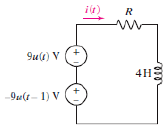
■ FIGURE 8.93
Expert Solution & Answer
Want to see the full answer?
Check out a sample textbook solution
Students have asked these similar questions
A source delivers an AC voltage of the form AV = 198 sin( 51 nt), where AV is in volts and t is in
seconds, to a capacitor. The maximum current in the circuit is 5.5 A. Find the value of the
capacitance (in micro Farad) and provide your answer with 1 decimal place.
Answer:
A circuit comprises an inductor of 9 H of negligible resistance connected in series with a 60 Ω resistor and a 240 V dc source. Determine the following:
(d) The time for current to reach 2.5 A in seconds.
(e) The initial rate of change of current in A/s.
9. In Figure 8, the switch S has been closed for a long time and the circuit
carries a constant current.
30 V
S
6kn
W
W
3ΚΩ
500 Ω
W
12μF
Figure 8.
(a) What is the voltage across the capacitor? Show your work or explain.
(b) Now the switch S is opened at t = 0. (Switch S is open for all questions below)
(i) What is the initial discharge current through the 50052 resistor?
(ii) How long does it take the capacitor to discharge to one-fifth of its original
voltage?
(iii) Determine the charge on the capacitor at time t = 0.05 s.
(iv) What is the amount of charge left on the capacitor after 75 time constants
has passed (t = 75RC).
Chapter 8 Solutions
Loose Leaf for Engineering Circuit Analysis Format: Loose-leaf
Ch. 8.1 - For the circuit in Fig. 8.2, what value of...Ch. 8.1 - Noting carefully how the circuit changes once the...Ch. 8.2 - In a source-free series RC circuit, find the...Ch. 8.3 - Prob. 4PCh. 8.3 - Prob. 5PCh. 8.4 - Prob. 6PCh. 8.4 - Prob. 7PCh. 8.4 - Prob. 8PCh. 8.5 - Evaluate each of the following at t = 0.8: (a)...Ch. 8.6 - For the circuit of Fig. 8.37, find vc(t) at t...
Ch. 8.7 - Prob. 11PCh. 8.7 - The voltage source 60 40u(t) V is in series with...Ch. 8.7 - Prob. 13PCh. 8.8 - Prob. 14PCh. 8.8 - Prob. 15PCh. 8 - A source-free RC circuit has R = 4 k and C = 22 F,...Ch. 8 - A source-free RC circuit has v(0) = 12 V and R =...Ch. 8 - The resistor in the circuit of Fig. 8.51 has been...Ch. 8 - Prob. 4ECh. 8 - Prob. 5ECh. 8 - Prob. 6ECh. 8 - Prob. 7ECh. 8 - Prob. 8ECh. 8 - Prob. 9ECh. 8 - The switch in Fig. 8.56 has been closed for a long...Ch. 8 - For the circuit in Fig. 8.56, find (a) the total...Ch. 8 - Design a capacitor-based circuit that can achieve...Ch. 8 - (a) Graph the function f (t) = 10e2t over the...Ch. 8 - The current i(t) flowing through a 1 k resistor is...Ch. 8 - Radiocarbon dating has a similar exponential time...Ch. 8 - For the circuit of Fig. 8.4, compute the time...Ch. 8 - Design a circuit which will produce a current of 1...Ch. 8 - Prob. 18ECh. 8 - Prob. 19ECh. 8 - Referring to the circuit shown in Fig. 8.11,...Ch. 8 - Prob. 21ECh. 8 - With the assumption that the switch in the circuit...Ch. 8 - The switch in Fig. 8.57 has been closed since...Ch. 8 - The switch in the circuit of Fig. 8.58 has been...Ch. 8 - Assuming the switch initially has been open for a...Ch. 8 - (a) Obtain an expression for v(t), the voltage...Ch. 8 - For the circuit of Fig. 8.61, determine ix, iL,...Ch. 8 - Prob. 28ECh. 8 - Prob. 29ECh. 8 - Prob. 30ECh. 8 - Prob. 31ECh. 8 - (a) Obtain an expression for vx as labeled in the...Ch. 8 - Prob. 33ECh. 8 - Prob. 34ECh. 8 - Prob. 35ECh. 8 - Prob. 36ECh. 8 - Prob. 37ECh. 8 - The switch in Fig. 8.70 is moved from A to B at t...Ch. 8 - Prob. 39ECh. 8 - Prob. 40ECh. 8 - Evaluate the following functions at t = 1, 0, and...Ch. 8 - Prob. 42ECh. 8 - Prob. 43ECh. 8 - Prob. 44ECh. 8 - You can use MATLAB to represent the unit-step...Ch. 8 - With reference to the circuit depicted in Fig....Ch. 8 - For the circuit given in Fig. 8.75, (a) determine...Ch. 8 - Prob. 48ECh. 8 - Prob. 49ECh. 8 - You build a portable solar charging circuit...Ch. 8 - The switch in the circuit of Fig. 8.78 has been...Ch. 8 - The switch in the circuit of Fig. 8.78 has been...Ch. 8 - Prob. 53ECh. 8 - Prob. 54ECh. 8 - Prob. 55ECh. 8 - For the circuit represented in Fig. 8.82, (a)...Ch. 8 - Prob. 58ECh. 8 - Prob. 59ECh. 8 - For the circuit given in Fig. 8.85, (a) determine...Ch. 8 - The circuit depicted in Fig. 8.86 contains two...Ch. 8 - Prob. 62ECh. 8 - Prob. 63ECh. 8 - A series RL circuit has a voltage that steps from...Ch. 8 - For the two-source circuit of Fig. 8.89, note that...Ch. 8 - (a) Obtain an expression for iL as labeled in Fig....Ch. 8 - Obtain an expression for i(t) as labeled in the...Ch. 8 - Obtain an expression for i1 as indicated in Fig....Ch. 8 - Plot the current i(t) in Fig. 8.93 if (a) R = 10 ;...Ch. 8 - A dc motor can be modeled as a series RL circuit...Ch. 8 - Prob. 71ECh. 8 - Prob. 72ECh. 8 - A series RC sequentially switched circuit has R =...Ch. 8 - Refer to the circuit of Fig. 8.95, which contains...Ch. 8 - In the circuit of Fig. 8.95, a 3 mF capacitor is...Ch. 8 - Prob. 78E
Knowledge Booster


Learn more about
Need a deep-dive on the concept behind this application? Look no further. Learn more about this topic, electrical-engineering and related others by exploring similar questions and additional content below.Similar questions
- b) What is the current at t = 0.008 s? (In [A]) c) What is the voltage at t = 0.008 s? (in [V]) Hint: What relationships exist between voltage and current when the current in an inductor is interrupted?arrow_forwardExercise#6: The current through a 250-mH inductor takes the following values. Calculate the expression for the voltage across the inductor in each case. a. i (t) = 5 sin 25t A b. i̟(t) : c. i (t) = 25 cos(100t + TT/3) A d. i (t) = 20 sin(10t – /12) A =-10 cos 50t Aarrow_forwardThe circuit shown in the figure is in steady state, when the switch is closed at t= 0.Assuming that the inductance is ideal, the current through the inductor at t= 0+ equals 10 Ω 10 V 10 mHarrow_forward
- With reference to the figure below, sketch the inductor voltage, vL, as a function of time, 0 < t < 60 ms. Solve also for the energy stored on the inductor at t = 40 ms. mV VL1 mV VL2 mV VL3 mV VL4 WL iL(A) 0.2 H ell r(ms) 10 20 30 50 60 40arrow_forwardmeggindia.com/2Form:Subject_test?User_Name=3709413000277732281&Number=3 Calculate the voltage across the capacitor v(t) and current through the inductor i(t) for t >0 for the following second order circuit. 4Ω v(1)=0.5 F t=0 2 H )30 V Answer Choices: a. v(t)=(2-18r)e V and i(r)= (10-9t)e A b. v(t)=(2-201)e V and i(t)=(10-10r)e A c. v(t)=(10-9) e V and i(1) = (2-20r) e A d. v(t)=(10-10r)e V and i(r)= (2-181)e A Answer A rch 37°F Me hp f9 |44 ins prt fo 10 12 fs IOI 23 3 $ 4 & 7 8 E Y F G J L C V alt ctri O V Σ トarrow_forwardThe EMF of 100 V is induced in a coil, when a current of 4 A collapses uniformly to zero in 2 8ms, the inductance of the coil is . (a) 200 H (b) 0.016 H (c) 0.016 mH (d) 0.1667 Harrow_forward
- + i(1) 50 mH 3v() 12 - A coil with an inductance of 50 mH is connected to a current source as shown in the figure. The expression for the change of current with time is: (0 A, i(t) = t 0 Which of the following is the function of change of coil voltage with time? Sov, O A) v(t) = {-0.2te-10t + 4e-10t V, t>0 t 0 t 0 t0arrow_forwardThe circuit shown in the figure is in steady state, when the switch is closed at t= 0.Assuming that the inductance is ideal, the current through the inductor at t= 0+ equals 10 2 10 V= 10 mHarrow_forwardThe figure below shows a capacitor, with capacitance C = 6.47 µF, and a resistor, with resistance R = 5.73 MQ, connected in series to a battery, with = 29.0 V. The circuit has a switch, which is initially open. C 8 + @ (a) What is the circuit's time constant (in seconds)? μC (b) What the maximum charge (in µC) on the capacitor after the switch is closed? (c) What is the current (in µA) through the resistor 10.0 s after the switch s closed? HAarrow_forward
- 8002 80V t=0 3F 0.5i(t) 30Ω www 5002 vi(t) The switch in the circuit has been closed for a long time. At t=0 the switch opens. a) Determine the voltage across the capacitor at t-0 b) For t>0, determine the resistance seen at the terminals of the capacitor and the time constant of the circuit. c) Determine i(t) for t>0.arrow_forwardIn a pulse power circuit, the voltage of a 10-μF capacitor is zero for t < 0 and v = 5(1−e−4000t) (t > 0). (a) Symbolically derive the current through the capacitor and the energy stored in the capacitor. (b) Check your derived results by checking numerically the current and the energy stored at t = 0 ms and t = 10 ms with the answers. (c) What are the numerical values of the capacitor’s voltage and current just before and after t = 0 (i.e., vc(0-) = vc(0+) and ic(0-) ≠ ic(0+)? Does this make physical sense? Answer: 200mA, 8.5×10⁻¹⁶ mA, 0J, 0.125 mJarrow_forwardUsing three capacitors each of capacitance 24µF, show how the student connects these three capacitors to provide a combined capacitance of (i) 16μ . (ii) 36μF. (ii) 8µF. Draw the circuit diagram along with the calculations for each case.arrow_forward
arrow_back_ios
SEE MORE QUESTIONS
arrow_forward_ios
Recommended textbooks for you
 Introductory Circuit Analysis (13th Edition)Electrical EngineeringISBN:9780133923605Author:Robert L. BoylestadPublisher:PEARSON
 Delmar's Standard Textbook Of ElectricityElectrical EngineeringISBN:9781337900348Author:Stephen L. HermanPublisher:Cengage Learning
 Programmable Logic ControllersElectrical EngineeringISBN:9780073373843Author:Frank D. PetruzellaPublisher:McGraw-Hill Education
 Fundamentals of Electric CircuitsElectrical EngineeringISBN:9780078028229Author:Charles K Alexander, Matthew SadikuPublisher:McGraw-Hill Education
 Electric Circuits. (11th Edition)Electrical EngineeringISBN:9780134746968Author:James W. Nilsson, Susan RiedelPublisher:PEARSON
 Engineering ElectromagneticsElectrical EngineeringISBN:9780078028151Author:Hayt, William H. (william Hart), Jr, BUCK, John A.Publisher:Mcgraw-hill Education,
Introductory Circuit Analysis (13th Edition)
Electrical Engineering
ISBN:9780133923605
Author:Robert L. Boylestad
Publisher:PEARSON
Delmar's Standard Textbook Of Electricity
Electrical Engineering
ISBN:9781337900348
Author:Stephen L. Herman
Publisher:Cengage Learning
Programmable Logic Controllers
Electrical Engineering
ISBN:9780073373843
Author:Frank D. Petruzella
Publisher:McGraw-Hill Education
Fundamentals of Electric Circuits
Electrical Engineering
ISBN:9780078028229
Author:Charles K Alexander, Matthew Sadiku
Publisher:McGraw-Hill Education
Electric Circuits. (11th Edition)
Electrical Engineering
ISBN:9780134746968
Author:James W. Nilsson, Susan Riedel
Publisher:PEARSON
Engineering Electromagnetics
Electrical Engineering
ISBN:9780078028151
Author:Hayt, William H. (william Hart), Jr, BUCK, John A.
Publisher:Mcgraw-hill Education,
ENA 9.2(1)(En)(Alex) Sinusoids & Phasors - Explanation with Example 9.1 ,9.2 & PP 9.2; Author: Electrical Engineering Academy;https://www.youtube.com/watch?v=vX_LLNl-ZpU;License: Standard YouTube License, CC-BY
Electrical Engineering: Ch 10 Alternating Voltages & Phasors (8 of 82) What is a Phasor?; Author: Michel van Biezen;https://www.youtube.com/watch?v=2I1tF3ixNg0;License: Standard Youtube License