
Loose Leaf for Engineering Circuit Analysis Format: Loose-leaf
9th Edition
ISBN: 9781259989452
Author: Hayt
Publisher: Mcgraw Hill Publishers
expand_more
expand_more
format_list_bulleted
Concept explainers
Videos
Textbook Question
Chapter 8, Problem 32E
(a) Obtain an expression for vx as labeled in the circuit of Fig. 8.65. (b) Evaluate vx at t = 5 ms. (c) Verify your answer with an appropriate SPICE simulation. (Hint: Define the circuit for t > 0 and define an initial value using the .ic SPICE directive.)
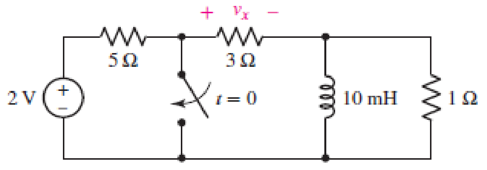
■ FIGURE 8.65
Expert Solution & Answer
Want to see the full answer?
Check out a sample textbook solution
Students have asked these similar questions
8.5 A 1100 Ah AGM battery (20-h rate) is used in a mini-grid. The mini-grid
supplies a critical load whose current draw is 25 A. Estimate the number of hours
the battery can supply this load if the Peukert exponent is 1.046.
2. Consider the circuit shown in the figure.
8.4 0
(a) What is the current, in amperes, on the 8.42
$1.40
4.20
resistor as soon as the switch S is closed?
V=16 V
(b) What is the current, in amperes, on the 4.22
resistor as soon as the switch S is closed?
(c) What is the current, in amperes, on the 4.22
resistor long after the switch S is closed?
(d) What is the charge on the capacitor, in units of pC, long after the switch is closed?
(c) What is the time-constant, 7, of the circuit in us?
(f) What is the charge on the capacitor att= 2r in uC?
8. Write down the expression of the follow circuits then try to simplified in possible:
(a)
(b)
Chapter 8 Solutions
Loose Leaf for Engineering Circuit Analysis Format: Loose-leaf
Ch. 8.1 - For the circuit in Fig. 8.2, what value of...Ch. 8.1 - Noting carefully how the circuit changes once the...Ch. 8.2 - In a source-free series RC circuit, find the...Ch. 8.3 - Prob. 4PCh. 8.3 - Prob. 5PCh. 8.4 - Prob. 6PCh. 8.4 - Prob. 7PCh. 8.4 - Prob. 8PCh. 8.5 - Evaluate each of the following at t = 0.8: (a)...Ch. 8.6 - For the circuit of Fig. 8.37, find vc(t) at t...
Ch. 8.7 - Prob. 11PCh. 8.7 - The voltage source 60 40u(t) V is in series with...Ch. 8.7 - Prob. 13PCh. 8.8 - Prob. 14PCh. 8.8 - Prob. 15PCh. 8 - A source-free RC circuit has R = 4 k and C = 22 F,...Ch. 8 - A source-free RC circuit has v(0) = 12 V and R =...Ch. 8 - The resistor in the circuit of Fig. 8.51 has been...Ch. 8 - Prob. 4ECh. 8 - Prob. 5ECh. 8 - Prob. 6ECh. 8 - Prob. 7ECh. 8 - Prob. 8ECh. 8 - Prob. 9ECh. 8 - The switch in Fig. 8.56 has been closed for a long...Ch. 8 - For the circuit in Fig. 8.56, find (a) the total...Ch. 8 - Design a capacitor-based circuit that can achieve...Ch. 8 - (a) Graph the function f (t) = 10e2t over the...Ch. 8 - The current i(t) flowing through a 1 k resistor is...Ch. 8 - Radiocarbon dating has a similar exponential time...Ch. 8 - For the circuit of Fig. 8.4, compute the time...Ch. 8 - Design a circuit which will produce a current of 1...Ch. 8 - Prob. 18ECh. 8 - Prob. 19ECh. 8 - Referring to the circuit shown in Fig. 8.11,...Ch. 8 - Prob. 21ECh. 8 - With the assumption that the switch in the circuit...Ch. 8 - The switch in Fig. 8.57 has been closed since...Ch. 8 - The switch in the circuit of Fig. 8.58 has been...Ch. 8 - Assuming the switch initially has been open for a...Ch. 8 - (a) Obtain an expression for v(t), the voltage...Ch. 8 - For the circuit of Fig. 8.61, determine ix, iL,...Ch. 8 - Prob. 28ECh. 8 - Prob. 29ECh. 8 - Prob. 30ECh. 8 - Prob. 31ECh. 8 - (a) Obtain an expression for vx as labeled in the...Ch. 8 - Prob. 33ECh. 8 - Prob. 34ECh. 8 - Prob. 35ECh. 8 - Prob. 36ECh. 8 - Prob. 37ECh. 8 - The switch in Fig. 8.70 is moved from A to B at t...Ch. 8 - Prob. 39ECh. 8 - Prob. 40ECh. 8 - Evaluate the following functions at t = 1, 0, and...Ch. 8 - Prob. 42ECh. 8 - Prob. 43ECh. 8 - Prob. 44ECh. 8 - You can use MATLAB to represent the unit-step...Ch. 8 - With reference to the circuit depicted in Fig....Ch. 8 - For the circuit given in Fig. 8.75, (a) determine...Ch. 8 - Prob. 48ECh. 8 - Prob. 49ECh. 8 - You build a portable solar charging circuit...Ch. 8 - The switch in the circuit of Fig. 8.78 has been...Ch. 8 - The switch in the circuit of Fig. 8.78 has been...Ch. 8 - Prob. 53ECh. 8 - Prob. 54ECh. 8 - Prob. 55ECh. 8 - For the circuit represented in Fig. 8.82, (a)...Ch. 8 - Prob. 58ECh. 8 - Prob. 59ECh. 8 - For the circuit given in Fig. 8.85, (a) determine...Ch. 8 - The circuit depicted in Fig. 8.86 contains two...Ch. 8 - Prob. 62ECh. 8 - Prob. 63ECh. 8 - A series RL circuit has a voltage that steps from...Ch. 8 - For the two-source circuit of Fig. 8.89, note that...Ch. 8 - (a) Obtain an expression for iL as labeled in Fig....Ch. 8 - Obtain an expression for i(t) as labeled in the...Ch. 8 - Obtain an expression for i1 as indicated in Fig....Ch. 8 - Plot the current i(t) in Fig. 8.93 if (a) R = 10 ;...Ch. 8 - A dc motor can be modeled as a series RL circuit...Ch. 8 - Prob. 71ECh. 8 - Prob. 72ECh. 8 - A series RC sequentially switched circuit has R =...Ch. 8 - Refer to the circuit of Fig. 8.95, which contains...Ch. 8 - In the circuit of Fig. 8.95, a 3 mF capacitor is...Ch. 8 - Prob. 78E
Additional Engineering Textbook Solutions
Find more solutions based on key concepts
When travelers from the USA and Canada visit Europe, they encounter a different power distribution system. Wall...
Electric machinery fundamentals
Identify the type of input and output configuration for each diff-amp in Figure 18-35.
Electronics Fundamentals: Circuits, Devices & Applications
Analog Voltmeter Design Figure P2-98(a) shows a voltmeter circuit consisting of a D'Arsonval meter, two series ...
ANALYSIS+DESIGN OF LINEAR CIRCUITS(LL)
Explain the main function of each of the following major components of a PLC: a. Processor module (CPU) b. I/O ...
Programmable Logic Controllers
Three point charges of equal magnitude q, that will yield a zero net electric field at the origin.
Engineering Electromagnetics
A constant voltage of 10V is applied to a 50H inductance, as shown in Figure P3.51 Figure P3 51 The current in ...
Electrical Engineering: Principles & Applications (7th Edition)
Knowledge Booster


Learn more about
Need a deep-dive on the concept behind this application? Look no further. Learn more about this topic, electrical-engineering and related others by exploring similar questions and additional content below.Similar questions
- 7) The circuit shown below is used to drive an LED with a voltage source. The circuit can also be thought of as a current amplifier in that, with the proper design, ip > i₁. (a) Derive the expression for ip in terms of i₁ and the resistors. (b) Design the circuit such that ip = 12 mA and i₁ = 1 mA for v₁ = 5 V. RE 210 R₁ www + R₂ Mli iD 7 Light OVOarrow_forwardCompute for the following values and show complete solutions. 1.) Norton's Equivalent a.) isc b.) iN c.) VN D.) Draw circuit equivalentarrow_forwardOne can assemble a “virtual” solar cell array by using playing cards, or business or index cards, to represent a solar cell. Combinations of these cards in series and/or parallel can model the required array output. a) Assume each card has an output of 0.5 V and a current (under bright light) of 2 A. Using your cards, how would you arrange them to produce an output of 6 A at 3 V (i.e. - 18 W)? b) Suppose you were told that you needed only 18 W (but no required voltage). Would you need more cards to make this arrangement?arrow_forward
- Part A Consider the circuit shown in the figure. A Q-point value for Ic between a minimum of 4 mA and a maximum of 5 mA is required. Assume that resistor values are constant and that B ranges from 95 to 310. It is desired for Rg to have the largest possible value while meeting the other constraints. (Figure 1) Determine the value of Rr. Express your answer to three significant figures and include the appropriate units. • View Available Hint(s) HA ? Rp = 29.9 Submit Previous Answers Request Answer X Incorrect; Try Again; 2 attempts remaining Part B Figure < 1 of 1 Determine the value of RE. Express your answer to three significant figures and include the appropriate units. • View Available Hint(s) +15 V RE = 765 N 1 kQ Submit Previous Answers RB VBEO = 0.7 V v Correct Here we learn how to solve the circuit with the BJT. 5 V RE Provide Feedback P Pearsonarrow_forwardQ3: You are designing a d'Arsonval movement instrument to operate as an Avometer. If the coil resistance is 2 k2, and the FSD current is 40 µA with a circuit battery of 8 V. Find the following: a. The standard resistor value for the series ohmmeter circuit. b. The shunt resistor value for the dc ammeter circuit to measure current as high as 200 mA. c. The multiplier resistor value for the dc voltmeter circuit to measure voltage as high as 10 V. d. The multiplier resistor value for the AC full-wave rectifier voltmeter circuit to measure voltage as high as 20 V rms with using germanium diodes. Note: Draw the circuit scheme for each of the above circuits.arrow_forwardA Stereo uses a 12 V DC power supply. At full volume, a maximum current of 1.4 A is drawn from the power supply. At minimum volume, the current drops to 200 mA. (a) You can simply consider the stereo as the load resistor RL. Calculate the range of R₁ at full volume and minimum volume. (b) Design a full-wave rectifier power supply using a 9.52:1 transformer. Assume that the outlet is 120 Vrms @ 60 Hz. Further assume that the diode turn-on voltage VD(on) is 0.7 V. Pick the value of C₁ such that vo has a maximum ripple of 1 Vp-p. Solve for the average value of v. = V. (note that this may be greater than 12 V) and iD(ave) = ID. (c) Add a series resistor to the secondary to limit the maximum surge current to 10 A if the secondary winding resistance of the transformer is 0.4 ohm. (d) Using PSPICE (with Is = 1 nA and n = 1.3 for the diodes), perform a transient simulation (.tran) and plot vo and Io(surge) for your max. and min. values of R₁. Make sure your transient simulation is long enough…arrow_forward
- 1.What factor(s) can contribute to differences between ideal theoretical values in a circuit and values measured in actual practice? A) Measurement inaccuracy B)Component tolerances C)Both (a) and (b). D)Neither (a) nor (b). 2.What maximum range of values could resistor R3 have and still be within tolerance assuming R3 is a 10% resistor? A) 3296.7 – 3303.3 Ω B) 2970 – 3630 Ω C) 3267 – 3333 Ω D) 2967 – 3633 Ω 3.A voltage of one volt applied across a resistance of one ohm produces a current of one ampere. What happens to the current if the voltage is doubled and the resistance is halve? A)It doubles. B)It increases four times. C)It increases three times. D)It remains the same. In Question 3, what is the current in amperes if the voltage is halved and the resistance is doubled? A) 1 ampere B) 33 ampere C) 5 ampere D) 25 amperearrow_forwardGiven the following table of voltage (V) and current (1) of a solar cell, a) Plot / versus V curve, b) Determine the following parameters: open circuit voltage (Voc), short circuit current (Isc), max power point (Pmp), voltage (Vmp) at Pmp, current (Imp) at Pmp and fill factor (FF) values of the solar cell, c) Taking input power of 1000W/m², calculate the efficiency of the solar cell. (Area of the solar cell is 156X156 cm²). Voltage (V) Current (A) 0 8.3 8.2 0.1 0.2 0.3 0.4 0.5 0.6 0.7 0.8 7.2 6.2 4.5 2.7 0 8.1 7.8arrow_forwardShown below is a typical setup for a solar battery system. Sun’s energy is converted to electricity using solar PV modules. To match the output voltage of the PV module to the battery's, a charge controller is used which is a DC-DC converter. The sun’s output power is given as 1000 W/m2. The solar module has a surface area of 1 m^2 with a conversion efficiency of 10%. A charge controller converts the 20V module voltage to 12V battery voltage, with an efficiency of 84% The battery is 12V with a capacity of 10Ah. Assuming the battery is half empty (or half full, depending on your personality) and the bulb is powered on, how long will it take for the battery to be fully charged? How long can the bulb be powered at night, assuming full battery when the sun goes down and that you can fully drain the battery? (answer in hours)arrow_forward
- 3. The network of Figure below is the basic biasing arrangement for the field-effect transistor (FET), a device of increasing importance in electronic design. (Biasing simply means the application of dc levels to establish a particular set of operating conditions.) Even though you may be unfamiliar with the FET, you can perform the following analysis using only the basic laws introduced in your lectures and the information provided on the diagram. a. Determine the voltages VG and Vs. b. Find the currents I1, I2, Ip, and Is. c. Determine Vps. d. Calculate VDG- VDD 16 V ID 2 MN Rp32.5 kM R1 오D VGO G I IG VGs = -1.75 V IG = 0 A Ip = Is VGS oVs |Is R2 270 kN Rs 1.5 kNarrow_forward3. The network of Figure below is the basic biasing arrangement for the field-effect transistor (FET), a device of increasing importance in electronic design. (Biasing simply means the application of dc levels to establish a particular set of operating conditions.) Even though you may be unfamiliar with the FET, you can perform the following analysis using only the basic laws introduced in your lectures and the information provided on the diagram. a. Determine the voltages VG and Vs. b. Find the currents I1, I2, Ip, and Is. c. Determine VDs. d. Calculate VDG. VDD = 16 V ID R132 MN R25 kN OD IG Vas = -1.75 V 4 Iç = 0A In = Is o's Is R2270 kN Rs1.5 kNarrow_forward3. The network of Figure below is the basic biasing arrangement for the field-effect transistor (FET), a device of increasing importance in electronic design. (Biasing simply means the application of dc levels to establish a particular set of operating conditions.) Even though you may be unfamiliar with the FET, you can perform the following analysis using only the basic laws introduced in your lectures and the information provided on the diagram. a. Determine the voltages Vg and Vs. b. Find the currents I1, I2, ID, and Is. c. Determine VDS- d. Calculate VDG. VDD 오 16 V \ID R1 2 ΜΩ Rp 2.5 kN 오D VGO VGs = -1.75 V V GS S IG = 0 A o's Ip = Is R2 270 kN Is Rs 1.5 kNarrow_forward
arrow_back_ios
SEE MORE QUESTIONS
arrow_forward_ios
Recommended textbooks for you
 Introductory Circuit Analysis (13th Edition)Electrical EngineeringISBN:9780133923605Author:Robert L. BoylestadPublisher:PEARSON
 Delmar's Standard Textbook Of ElectricityElectrical EngineeringISBN:9781337900348Author:Stephen L. HermanPublisher:Cengage Learning
 Programmable Logic ControllersElectrical EngineeringISBN:9780073373843Author:Frank D. PetruzellaPublisher:McGraw-Hill Education
 Fundamentals of Electric CircuitsElectrical EngineeringISBN:9780078028229Author:Charles K Alexander, Matthew SadikuPublisher:McGraw-Hill Education
 Electric Circuits. (11th Edition)Electrical EngineeringISBN:9780134746968Author:James W. Nilsson, Susan RiedelPublisher:PEARSON
 Engineering ElectromagneticsElectrical EngineeringISBN:9780078028151Author:Hayt, William H. (william Hart), Jr, BUCK, John A.Publisher:Mcgraw-hill Education,
Introductory Circuit Analysis (13th Edition)
Electrical Engineering
ISBN:9780133923605
Author:Robert L. Boylestad
Publisher:PEARSON
Delmar's Standard Textbook Of Electricity
Electrical Engineering
ISBN:9781337900348
Author:Stephen L. Herman
Publisher:Cengage Learning
Programmable Logic Controllers
Electrical Engineering
ISBN:9780073373843
Author:Frank D. Petruzella
Publisher:McGraw-Hill Education
Fundamentals of Electric Circuits
Electrical Engineering
ISBN:9780078028229
Author:Charles K Alexander, Matthew Sadiku
Publisher:McGraw-Hill Education
Electric Circuits. (11th Edition)
Electrical Engineering
ISBN:9780134746968
Author:James W. Nilsson, Susan Riedel
Publisher:PEARSON
Engineering Electromagnetics
Electrical Engineering
ISBN:9780078028151
Author:Hayt, William H. (william Hart), Jr, BUCK, John A.
Publisher:Mcgraw-hill Education,
ENA 9.2(1)(En)(Alex) Sinusoids & Phasors - Explanation with Example 9.1 ,9.2 & PP 9.2; Author: Electrical Engineering Academy;https://www.youtube.com/watch?v=vX_LLNl-ZpU;License: Standard YouTube License, CC-BY
Electrical Engineering: Ch 10 Alternating Voltages & Phasors (8 of 82) What is a Phasor?; Author: Michel van Biezen;https://www.youtube.com/watch?v=2I1tF3ixNg0;License: Standard Youtube License