
Loose Leaf for Engineering Circuit Analysis Format: Loose-leaf
9th Edition
ISBN: 9781259989452
Author: Hayt
Publisher: Mcgraw Hill Publishers
expand_more
expand_more
format_list_bulleted
Concept explainers
Videos
Textbook Question
Chapter 8.1, Problem 1P
For the circuit in Fig. 8.2, what value of capacitance would be required to ensure that v(t) < V0/10 for t > 10 ms?
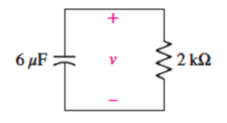
FIGURE 8.2
Expert Solution & Answer
Want to see the full answer?
Check out a sample textbook solution
Students have asked these similar questions
2. Consider the circuit shown in the figure.
8.4 0
(a) What is the current, in amperes, on the 8.42
$1.40
4.20
resistor as soon as the switch S is closed?
V=16 V
(b) What is the current, in amperes, on the 4.22
resistor as soon as the switch S is closed?
(c) What is the current, in amperes, on the 4.22
resistor long after the switch S is closed?
(d) What is the charge on the capacitor, in units of pC, long after the switch is closed?
(c) What is the time-constant, 7, of the circuit in us?
(f) What is the charge on the capacitor att= 2r in uC?
resis to r
in du cto r
wired
are
in series of
an d
an
i deal
an
battery. The
in ductance
of the
in ductorrs
8.0 mH.
and
the
resis tance
of the
battery
is connected to the resirtor
2.0s2.
Assume
the
Hle
How long
does it
ta ke the
and
inductor
at t>0.
of its
final steady ete
value?
Current
to
reach
half
8.5 A 1100 Ah AGM battery (20-h rate) is used in a mini-grid. The mini-grid
supplies a critical load whose current draw is 25 A. Estimate the number of hours
the battery can supply this load if the Peukert exponent is 1.046.
Chapter 8 Solutions
Loose Leaf for Engineering Circuit Analysis Format: Loose-leaf
Ch. 8.1 - For the circuit in Fig. 8.2, what value of...Ch. 8.1 - Noting carefully how the circuit changes once the...Ch. 8.2 - In a source-free series RC circuit, find the...Ch. 8.3 - Prob. 4PCh. 8.3 - Prob. 5PCh. 8.4 - Prob. 6PCh. 8.4 - Prob. 7PCh. 8.4 - Prob. 8PCh. 8.5 - Evaluate each of the following at t = 0.8: (a)...Ch. 8.6 - For the circuit of Fig. 8.37, find vc(t) at t...
Ch. 8.7 - Prob. 11PCh. 8.7 - The voltage source 60 40u(t) V is in series with...Ch. 8.7 - Prob. 13PCh. 8.8 - Prob. 14PCh. 8.8 - Prob. 15PCh. 8 - A source-free RC circuit has R = 4 k and C = 22 F,...Ch. 8 - A source-free RC circuit has v(0) = 12 V and R =...Ch. 8 - The resistor in the circuit of Fig. 8.51 has been...Ch. 8 - Prob. 4ECh. 8 - Prob. 5ECh. 8 - Prob. 6ECh. 8 - Prob. 7ECh. 8 - Prob. 8ECh. 8 - Prob. 9ECh. 8 - The switch in Fig. 8.56 has been closed for a long...Ch. 8 - For the circuit in Fig. 8.56, find (a) the total...Ch. 8 - Design a capacitor-based circuit that can achieve...Ch. 8 - (a) Graph the function f (t) = 10e2t over the...Ch. 8 - The current i(t) flowing through a 1 k resistor is...Ch. 8 - Radiocarbon dating has a similar exponential time...Ch. 8 - For the circuit of Fig. 8.4, compute the time...Ch. 8 - Design a circuit which will produce a current of 1...Ch. 8 - Prob. 18ECh. 8 - Prob. 19ECh. 8 - Referring to the circuit shown in Fig. 8.11,...Ch. 8 - Prob. 21ECh. 8 - With the assumption that the switch in the circuit...Ch. 8 - The switch in Fig. 8.57 has been closed since...Ch. 8 - The switch in the circuit of Fig. 8.58 has been...Ch. 8 - Assuming the switch initially has been open for a...Ch. 8 - (a) Obtain an expression for v(t), the voltage...Ch. 8 - For the circuit of Fig. 8.61, determine ix, iL,...Ch. 8 - Prob. 28ECh. 8 - Prob. 29ECh. 8 - Prob. 30ECh. 8 - Prob. 31ECh. 8 - (a) Obtain an expression for vx as labeled in the...Ch. 8 - Prob. 33ECh. 8 - Prob. 34ECh. 8 - Prob. 35ECh. 8 - Prob. 36ECh. 8 - Prob. 37ECh. 8 - The switch in Fig. 8.70 is moved from A to B at t...Ch. 8 - Prob. 39ECh. 8 - Prob. 40ECh. 8 - Evaluate the following functions at t = 1, 0, and...Ch. 8 - Prob. 42ECh. 8 - Prob. 43ECh. 8 - Prob. 44ECh. 8 - You can use MATLAB to represent the unit-step...Ch. 8 - With reference to the circuit depicted in Fig....Ch. 8 - For the circuit given in Fig. 8.75, (a) determine...Ch. 8 - Prob. 48ECh. 8 - Prob. 49ECh. 8 - You build a portable solar charging circuit...Ch. 8 - The switch in the circuit of Fig. 8.78 has been...Ch. 8 - The switch in the circuit of Fig. 8.78 has been...Ch. 8 - Prob. 53ECh. 8 - Prob. 54ECh. 8 - Prob. 55ECh. 8 - For the circuit represented in Fig. 8.82, (a)...Ch. 8 - Prob. 58ECh. 8 - Prob. 59ECh. 8 - For the circuit given in Fig. 8.85, (a) determine...Ch. 8 - The circuit depicted in Fig. 8.86 contains two...Ch. 8 - Prob. 62ECh. 8 - Prob. 63ECh. 8 - A series RL circuit has a voltage that steps from...Ch. 8 - For the two-source circuit of Fig. 8.89, note that...Ch. 8 - (a) Obtain an expression for iL as labeled in Fig....Ch. 8 - Obtain an expression for i(t) as labeled in the...Ch. 8 - Obtain an expression for i1 as indicated in Fig....Ch. 8 - Plot the current i(t) in Fig. 8.93 if (a) R = 10 ;...Ch. 8 - A dc motor can be modeled as a series RL circuit...Ch. 8 - Prob. 71ECh. 8 - Prob. 72ECh. 8 - A series RC sequentially switched circuit has R =...Ch. 8 - Refer to the circuit of Fig. 8.95, which contains...Ch. 8 - In the circuit of Fig. 8.95, a 3 mF capacitor is...Ch. 8 - Prob. 78E
Additional Engineering Textbook Solutions
Find more solutions based on key concepts
How many coulombs do 93.8 1016 electrons represent?
Principles Of Electric Circuits
What is the color code for a 365- five-band precision resistor with a tolerance of 5 percent?
ELECTRICITY FOR TRADES (LOOSELEAF)
Identify the type of input and output configuration for each diff-amp in Figure 18-35.
Electronics Fundamentals: Circuits, Devices & Applications
Write the nodal equations for the network of Fig. 8.137 using the general approach. Find the nodal voltages usi...
Introductory Circuit Analysis (13th Edition)
For the “tank” circuit in Fig. 14.79, find the resonant frequency.
Figure 14.79
For Probs. 14.39, 14.71, and 1...
Fundamentals of Electric Circuits
When travelers from the USA and Canada visit Europe, they encounter a different power distribution system. Wall...
Electric machinery fundamentals
Knowledge Booster


Learn more about
Need a deep-dive on the concept behind this application? Look no further. Learn more about this topic, electrical-engineering and related others by exploring similar questions and additional content below.Similar questions
- 8. In the figure at the left is shown part of the circuit that is used to model the cell membrane of an electrically excitable cell.* While the actual model includes variable resistors, let's analyze the simplest example of this circuit: take the batteries to be identical and ideal and the resistors to be identical and Ohmic. The capacitor plates (inside the plastic shell shown) correspond to the inside and outside of the membrane. capacitor R: Duracell resistors batteries Duracell Duracell R₂ Suppose the batteries each are labeled with a voltage V, and the resistors each have a resistance R. Where asked for currents or voltages express your answers in terms of V, and R. A. Note that the batteries are not all connected with the same orientation. When the network reaches a steady state is there any current through the batteries and resistors? Explain briefly why you think so. .B. If you think that there is no current in the batteries and resistors in the steady state, find the voltage…arrow_forwardCapacitance= 9uF Determine the time constant of the circuit for the capacities. For the capacity value, calculate the estimated time to come to the final state. Plot capacitor current and voltage graphs and show if it works in harmony with the time constant you calculated. NOTE: if you want you can use falstad online circuit simulator.arrow_forwardQ/Design a circuit to limit a (20 Vrms) sinusoidal voltage to a maximum positive amplitude of (10 V) and a maximum negative amplitude of using a single (14 V) dc voltage source.arrow_forward
- 8.3 For a Si solar cell, the dark saturation current is 2 μA and the short circuit cur- rent is 150 mA. When it is optically illuminated, the optically generated current is 0.1 mA. Find the corresponding voltage at current of 100 mA. please tell me his problem in detailarrow_forwardA source provides a sinusoidal current is (t) of 60 Hz to two resistors and a capacitor, so that a current ic (t) flows through this last element. a) Indicate under which conditions ic (t) would be late with respect to is (t), under which conditions it would be in phase and under which conditions it would be earlyb) If C increased and the rest of the circuit remained the same, indicate whether the effective value of ic (t) would increase or decreasearrow_forwardThe leaf of a corn plant has a resistance of 2.0M Ohms, asmeasured between two electrodes placed 30cm apart along the leaf. The leaf has a width of 3.5cm, a thickness of 0.2mm, and a length of 40cm. Its top & bottom surfaces are shaped like flat plates. The fluid within the leaf is mostly water. What is its capacitance? A) 8.85picoFB) 0.049 micro FC) 495600 FD) 80Farrow_forward
- 8. A resistor, inductor, and capacitor are in series in a circuit where the frequency can vary from zero to a very high value that we can assume is infinity. At the frequency wo, the magnitudes of the impedances of these elements are equal. (Both = 0 and w = ∞ are considered valid frequencies.) (a) In sinusoidal steady state, can this series combination appear as a short circuit? If so, what should the frequency be? (b) In sinusoidal steady state, can this series combination appear as an open circuit? If so, what should the frequency be?arrow_forwardAn RLC circuit is composed of a 30,a 500 mH Induc tor, ond a 200 MF copacitor. If the capactar is initially charged with a 90 V volt source while the switch is Open, what will be the currént in the circuit 0.04 seconds after the switch is closed (removing the volt source from the Circuit)?arrow_forwardin a circuit containing a resistor, inductor and capacitor in series, if the voltage drops are given as 40v at resistor, 50v at inductor and 20v at capacitor, calculate the voltage supplied by ac sourcearrow_forward
- Consider the battery-charging circuit shown in Figure 9.25 on page 476, in which vs(t) = 20 sin(200πt) , R = 80 Ω , VB = 12 V and the diode is ideal. a. Sketch the current i(t) to scale versus time. b. Determine the average charging current for the battery.arrow_forwardA string of thyristor is connected in series to withstand a DC voltage of 11 kV. The maximum leakage current and recovery charge difference of 150 mA and 250 µC. Respectively consider the string efficiency of 85% and maximum voltage across each SCR is 1000 V. Dynamic equalizing capacitance and static equalizing resistance are respectively.arrow_forwardQuestions Q1) what is meant by Insolation, ARC in solar systems? Q2) mention the types of solar systems? Q3) explain with drawing the main components of solar system. Q4) explain with equations the intuitive technique for design pv/battery system. Q5) Discuss all the results in Tables (1 to 3). Q6) Referring to Tables (4) & (5); draw & discuss the relations: 1. (I VS THD of current), 2. (V Vs Q).arrow_forward
arrow_back_ios
SEE MORE QUESTIONS
arrow_forward_ios
Recommended textbooks for you
 Introductory Circuit Analysis (13th Edition)Electrical EngineeringISBN:9780133923605Author:Robert L. BoylestadPublisher:PEARSON
 Delmar's Standard Textbook Of ElectricityElectrical EngineeringISBN:9781337900348Author:Stephen L. HermanPublisher:Cengage Learning
 Programmable Logic ControllersElectrical EngineeringISBN:9780073373843Author:Frank D. PetruzellaPublisher:McGraw-Hill Education
 Fundamentals of Electric CircuitsElectrical EngineeringISBN:9780078028229Author:Charles K Alexander, Matthew SadikuPublisher:McGraw-Hill Education
 Electric Circuits. (11th Edition)Electrical EngineeringISBN:9780134746968Author:James W. Nilsson, Susan RiedelPublisher:PEARSON
 Engineering ElectromagneticsElectrical EngineeringISBN:9780078028151Author:Hayt, William H. (william Hart), Jr, BUCK, John A.Publisher:Mcgraw-hill Education,
Introductory Circuit Analysis (13th Edition)
Electrical Engineering
ISBN:9780133923605
Author:Robert L. Boylestad
Publisher:PEARSON
Delmar's Standard Textbook Of Electricity
Electrical Engineering
ISBN:9781337900348
Author:Stephen L. Herman
Publisher:Cengage Learning
Programmable Logic Controllers
Electrical Engineering
ISBN:9780073373843
Author:Frank D. Petruzella
Publisher:McGraw-Hill Education
Fundamentals of Electric Circuits
Electrical Engineering
ISBN:9780078028229
Author:Charles K Alexander, Matthew Sadiku
Publisher:McGraw-Hill Education
Electric Circuits. (11th Edition)
Electrical Engineering
ISBN:9780134746968
Author:James W. Nilsson, Susan Riedel
Publisher:PEARSON
Engineering Electromagnetics
Electrical Engineering
ISBN:9780078028151
Author:Hayt, William H. (william Hart), Jr, BUCK, John A.
Publisher:Mcgraw-hill Education,
ENA 9.2(1)(En)(Alex) Sinusoids & Phasors - Explanation with Example 9.1 ,9.2 & PP 9.2; Author: Electrical Engineering Academy;https://www.youtube.com/watch?v=vX_LLNl-ZpU;License: Standard YouTube License, CC-BY
Electrical Engineering: Ch 10 Alternating Voltages & Phasors (8 of 82) What is a Phasor?; Author: Michel van Biezen;https://www.youtube.com/watch?v=2I1tF3ixNg0;License: Standard Youtube License