
Loose Leaf for Engineering Circuit Analysis Format: Loose-leaf
9th Edition
ISBN: 9781259989452
Author: Hayt
Publisher: Mcgraw Hill Publishers
expand_more
expand_more
format_list_bulleted
Concept explainers
Videos
Textbook Question
Chapter 13, Problem 12E
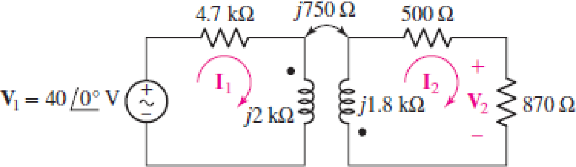
For the circuit of Fig. 13.41, calculate I1, I2, V2/V1, and I2/I1.
FIGURE 13.41
Expert Solution & Answer
Want to see the full answer?
Check out a sample textbook solution
Students have asked these similar questions
20 log₁0|H(0)|, dB
Design a circuit that has the asymptotic magnitude Bode plot shown below.
Assume C1 = 0.1uF
32
12
400
4 k
40 k
(0 ad/s, log scale)
40
In the d.c. network shown in Fig.13.47, A is the
feeding point and Is maintained at 250 V. The
resistances of the various branches (go and
return) are indicated in the figure. Determine the
current in each branch.
+ 12 A
0.4 a
36 A
0.8 Q
+ 16 A
0.40
8A
D
Fig. 1347
Ans:- [AB = 144A ; BC = 2A ; DC = 5A ; AD = 13A]
0.8 a
04 a
39. Select values for a and h in the circuit of Fig. 13.65 so that the ideal source
supplies 1000 W, half of which is delivered to the 100-2 load.
25 N
1:a
1:b
100 N
100 V rms
b = 0.8944, a = 5
elll
ell
ell
ell
Chapter 13 Solutions
Loose Leaf for Engineering Circuit Analysis Format: Loose-leaf
Ch. 13.1 - Assuming M = 10 H, coil L2 is open-circuited, and...Ch. 13.1 - For the circuit of Fig. 13.9, write appropriate...Ch. 13.1 - For the circuit of Fig. 13.11, write an...Ch. 13.2 - Let is = 2 cos 10t A in the circuit of Fig. 13.14,...Ch. 13.3 - Element values for a certain linear transformer...Ch. 13.3 - (a) If the two networks shown in Fig. 13.20 are...Ch. 13.3 - If the networks in Fig. 13.23 are equivalent,...Ch. 13.4 - Prob. 8PCh. 13.4 - Let N1 = 1000 turns and N2 = 5000 turns in the...Ch. 13 - Prob. 1E
Ch. 13 - With respect to Fig. 13.36, assume L1 = 500 mH, L2...Ch. 13 - The circuit in Fig. 13.36 has a sinusoidal input...Ch. 13 - Prob. 4ECh. 13 - Prob. 5ECh. 13 - The circuit in Fig. 13.38 has a sinusoidal input...Ch. 13 - The physical construction of three pairs of...Ch. 13 - Prob. 8ECh. 13 - Prob. 9ECh. 13 - Calculate v1 and v2 if i1 = 5 sin 40t mA and i2 =...Ch. 13 - Prob. 11ECh. 13 - For the circuit of Fig. 13.41, calculate I1, I2,...Ch. 13 - Prob. 13ECh. 13 - Prob. 14ECh. 13 - In the circuit of Fig. 13.43, M is reduced by an...Ch. 13 - Prob. 16ECh. 13 - Prob. 17ECh. 13 - Prob. 18ECh. 13 - Prob. 19ECh. 13 - Note that there is no mutual coupling between the...Ch. 13 - Prob. 21ECh. 13 - (a) Find Zin(j) for the network of Fig 13.50. (b)...Ch. 13 - For the coupled coils of Fig. 13.51, L1 = L2 = 10...Ch. 13 - Prob. 24ECh. 13 - Prob. 25ECh. 13 - Prob. 26ECh. 13 - Consider the circuit represented in Fig. 13.53....Ch. 13 - Compute v1, v2, and the average power delivered to...Ch. 13 - Assume the following values for the circuit...Ch. 13 - Prob. 30ECh. 13 - Prob. 31ECh. 13 - Prob. 32ECh. 13 - Prob. 33ECh. 13 - Prob. 34ECh. 13 - Prob. 35ECh. 13 - Prob. 36ECh. 13 - Prob. 37ECh. 13 - FIGURE 13.60 For the circuit of Fig. 13.60, redraw...Ch. 13 - Prob. 39ECh. 13 - Prob. 40ECh. 13 - Calculate the average power delivered to the 400 m...Ch. 13 - Prob. 42ECh. 13 - Calculate the average power delivered to each...Ch. 13 - Prob. 44ECh. 13 - Prob. 45ECh. 13 - Prob. 46ECh. 13 - Prob. 47ECh. 13 - Prob. 48ECh. 13 - A transformer whose nameplate reads 2300/230 V, 25...Ch. 13 - Prob. 52ECh. 13 - As the lead singer in the local rock band, you...Ch. 13 - Obtain an expression for V2/Vs in the circuit of...Ch. 13 - Prob. 55E
Knowledge Booster


Learn more about
Need a deep-dive on the concept behind this application? Look no further. Learn more about this topic, electrical-engineering and related others by exploring similar questions and additional content below.Similar questions
- Fig. 13.46 B + 12 A 0.4 2 36 A A 0.8 2 16 A In the d.c. network shown in Fig.13.47, A is the feeding point and is maintained at 250 V. The resistances 3. 0.4 2 8 A Fig. 13.47 of the various branches (go and return) are indicated in the figure. Determine the current in each branch. [AB = 144A ; BC = 2A ; DC = 5A ; AD = 13A] 0.8 2 0 0.4 2arrow_forward18. For the circuit of Fig. 13.47, find the currents i(t), i2(1), and i3(t) if f = 60 Hz. %3D 50 4 H ell 3 H 2 sin 31 V ( 10 H 12 0 I3 elearrow_forwardDiscussion: [12] 1.In both circuits of this exercise the negative terminals of the sources are connected to ground. Is this a requirement for mesh analysis? What would happen to the mesh currents if the positions of El and R1 in Figure (15) were swapped? 2.The circuits of Figures (15) and (16) had been analyzed previously in the Superposition Theorem exercise. How do the results of this exercise compare to the earlier results? Should the resulting currents and voltages be identical? If not, what sort of things might affect the outcome?arrow_forward
- 13. Applying Thevenin’s theorem, calculate the current (showing its direction) in the 13 ohms resistor of circuit given in Figure 13. [Ans: 168.7 V; and 8.31A]arrow_forwardRefer to Fig. 13.43. If the two-winding transformer is a 60-VA,120V/10V transformer, what is the power rating of the autotransformer? 4 A V, = 12 V 0.2 A 4 A 4.2 A 252 V + 0.2 A 240 v V, 3||E v., 12 V 240 V = 240 V (a) (b) Figure 13.43 For Example 13.10.arrow_forwardFundamentals of Electrical Engineering 2020/2021 Dr. Yaseen H. Tahir We can note that IL and Vi are same in both cases. Example: a) Convert the current source of Figure below to an equivalent voltage source. b) Prove your answer. (Home work) Rs 10KQ 20KO 5 mA b.arrow_forward
- Fundamentals of Electrical Engineering 2020/2021 Dr. Yaseen H. Tahir We can note that IL and VL are same in both cases. Example: a) Convert the current soure of Figure below to an equivalent voltage source. b) Prove your answer. (Home work) a R Rs 10KΩ 20KO 5 mAarrow_forwardQ.1. A power suppply having 220 V AC input and two fixed outputs as 10 V DC and 20 V DC is requested from you. For this purpose, a transformer with 220 V AC input / 15 V AC output, some capacitors, some silicon diodes, and zener diodes are presented.a) Design your power supply and point out DC voltage outputs b) Explain the operation of the network and all the components used in the design .c) Calculate and plot input and output signals of the network.Hint: For design, remember clipper, clamper, rectifier,voltage multiplier and zener circuitsarrow_forwardRefer to the autotransformer circuit in Fig. 13.44. Calculate: (a) I₁, I₂, and I, if Z₁ = 8 + j6, and (b) the complex power supplied to the load. 1₂ 120/30⁰ Vrms eeeee *+ 120 turns 80 turns V₂ 74₁ Zarrow_forward
- TUTORIAL PROBLEMS 1. A 300 m ring distributor has loads as shown in Fig. 13.45 where distances are tance of each conductor is 0-2 W per 1000 metres and the loads are tapped off at points B, C and D as metres. The resis- shown. If the distributor is fed at A at 240 V, find voltages at B, C and D. IV - 236-9 V ; V- 235-97 V ; V, - 237-45 V| 240 V 30 A 10 A E 70 D 50 A A 60 D 100 A 230 V + 20 A A 80 90 70 A 10 A Fig, 13.45 Fig. 13.46 A d.c. 2-wire ring main ABCDEA is fed from 230 V supply as shown in Fig. 13.46. The resistance of each section (go and re- turn) AB, BC, CD, DE and EA is 0-1 W. The loads are tapped off as shown. Find the voltage at each load point. |V½ = 227 V ; Vc-225 V ; V,- 225 V; VE = 226 V] In the d.c. network shown in Fig.13.47, A is the feeding point and is maintained at 250 V. The resistances 2. B. 12 A 0.4 2 36 A A 0.8 2 16 A 0.4 2 3. 8A D Fig. 13.47 of the various branches (go and return) are indicated in the figure. Determine the current in each branch. JAB - 144A…arrow_forwardSection 13.4 Linear Transformers 13.29 In the circuit of Fig. 13.98, find the value of the coupling coefficient k that will make the 10-N resistor dissipate 320 W. For this value of k, find the energy stored in the coupled coils at t = 1.5 s. k 10 Q 165 cos 10³t V 30 mH 50 mH 20 2 llarrow_forwardQuestion 4: Obtain the Thevenin equivalent circuit for the circuit in Fig. 13.83 at terminals a-b. 50/90° V (+ 5Ω Figure 13.83 m j6Ω j2 Ω α b m j8 Ω -j3 Ω 2 Ω Μ 20/0° Aarrow_forward
arrow_back_ios
SEE MORE QUESTIONS
arrow_forward_ios
Recommended textbooks for you
 Introductory Circuit Analysis (13th Edition)Electrical EngineeringISBN:9780133923605Author:Robert L. BoylestadPublisher:PEARSON
 Delmar's Standard Textbook Of ElectricityElectrical EngineeringISBN:9781337900348Author:Stephen L. HermanPublisher:Cengage Learning
 Programmable Logic ControllersElectrical EngineeringISBN:9780073373843Author:Frank D. PetruzellaPublisher:McGraw-Hill Education
 Fundamentals of Electric CircuitsElectrical EngineeringISBN:9780078028229Author:Charles K Alexander, Matthew SadikuPublisher:McGraw-Hill Education
 Electric Circuits. (11th Edition)Electrical EngineeringISBN:9780134746968Author:James W. Nilsson, Susan RiedelPublisher:PEARSON
 Engineering ElectromagneticsElectrical EngineeringISBN:9780078028151Author:Hayt, William H. (william Hart), Jr, BUCK, John A.Publisher:Mcgraw-hill Education,
Introductory Circuit Analysis (13th Edition)
Electrical Engineering
ISBN:9780133923605
Author:Robert L. Boylestad
Publisher:PEARSON
Delmar's Standard Textbook Of Electricity
Electrical Engineering
ISBN:9781337900348
Author:Stephen L. Herman
Publisher:Cengage Learning
Programmable Logic Controllers
Electrical Engineering
ISBN:9780073373843
Author:Frank D. Petruzella
Publisher:McGraw-Hill Education
Fundamentals of Electric Circuits
Electrical Engineering
ISBN:9780078028229
Author:Charles K Alexander, Matthew Sadiku
Publisher:McGraw-Hill Education
Electric Circuits. (11th Edition)
Electrical Engineering
ISBN:9780134746968
Author:James W. Nilsson, Susan Riedel
Publisher:PEARSON
Engineering Electromagnetics
Electrical Engineering
ISBN:9780078028151
Author:Hayt, William H. (william Hart), Jr, BUCK, John A.
Publisher:Mcgraw-hill Education,
How does a Transformer work - Working Principle electrical engineering; Author: The Engineering Mindset;https://www.youtube.com/watch?v=UchitHGF4n8;License: Standard Youtube License