
Loose Leaf for Engineering Circuit Analysis Format: Loose-leaf
9th Edition
ISBN: 9781259989452
Author: Hayt
Publisher: Mcgraw Hill Publishers
expand_more
expand_more
format_list_bulleted
Videos
Textbook Question
Chapter 13, Problem 3E
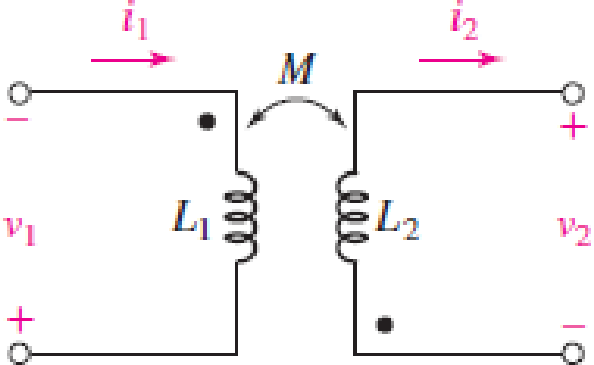
The circuit in Fig. 13.36 has a sinusoidal input at ω=2,000 rad/s with 
 and 100 Ω resistor attached across the terminals labeled v2. For the case where L1 = 400 mH, L2 = 100 mH, and M = 50 mH, determine V1, I2, and V2 in phasor form.
FIGURE 13.36
Expert Solution & Answer
Want to see the full answer?
Check out a sample textbook solution
Students have asked these similar questions
The zero-state scaled network shown in Figure 134 is driven by the sinusoidal current
source Jg(t) expressed as
J,(1)= 12 sin (21 - 45°) A
Use phasors and complex immittances to calculate the following:
(a)
the node voltages Vnl and Vn2 as complex numbers in rectangular and polar format,
and
(b) the node voltages vn1 (t) and vn2(t) in the time-domain.
L2
0.5H
Vn1(t)
Vn2(t)
+
V2(t)
Jg(t)
9mV2(t)
C3 1F
R1
(gm = 3S)
Figure 134
Scaled RLC network
An impedance coil is connected in series with a capacitor across a 220 V, 60 Hz acsupply. The circuit is designed such that the voltage across the impedance coil and thecapacitor are numerically equal. If this circuit operates at 0.866025403 leading powerfactor, determine the apparent power of the coil when the circuit current is 1 A.
please answer asap
70. Ideal inductors and capacitors are 90 degrees out of phase with each other.
True
False
71. Ideal inductors and resistors are 180 degrees out of phase with each other.
True
False
72. Impedance of a circuit can be represented or expressed in complex form.
True
False
Chapter 13 Solutions
Loose Leaf for Engineering Circuit Analysis Format: Loose-leaf
Ch. 13.1 - Assuming M = 10 H, coil L2 is open-circuited, and...Ch. 13.1 - For the circuit of Fig. 13.9, write appropriate...Ch. 13.1 - For the circuit of Fig. 13.11, write an...Ch. 13.2 - Let is = 2 cos 10t A in the circuit of Fig. 13.14,...Ch. 13.3 - Element values for a certain linear transformer...Ch. 13.3 - (a) If the two networks shown in Fig. 13.20 are...Ch. 13.3 - If the networks in Fig. 13.23 are equivalent,...Ch. 13.4 - Prob. 8PCh. 13.4 - Let N1 = 1000 turns and N2 = 5000 turns in the...Ch. 13 - Prob. 1E
Ch. 13 - With respect to Fig. 13.36, assume L1 = 500 mH, L2...Ch. 13 - The circuit in Fig. 13.36 has a sinusoidal input...Ch. 13 - Prob. 4ECh. 13 - Prob. 5ECh. 13 - The circuit in Fig. 13.38 has a sinusoidal input...Ch. 13 - The physical construction of three pairs of...Ch. 13 - Prob. 8ECh. 13 - Prob. 9ECh. 13 - Calculate v1 and v2 if i1 = 5 sin 40t mA and i2 =...Ch. 13 - Prob. 11ECh. 13 - For the circuit of Fig. 13.41, calculate I1, I2,...Ch. 13 - Prob. 13ECh. 13 - Prob. 14ECh. 13 - In the circuit of Fig. 13.43, M is reduced by an...Ch. 13 - Prob. 16ECh. 13 - Prob. 17ECh. 13 - Prob. 18ECh. 13 - Prob. 19ECh. 13 - Note that there is no mutual coupling between the...Ch. 13 - Prob. 21ECh. 13 - (a) Find Zin(j) for the network of Fig 13.50. (b)...Ch. 13 - For the coupled coils of Fig. 13.51, L1 = L2 = 10...Ch. 13 - Prob. 24ECh. 13 - Prob. 25ECh. 13 - Prob. 26ECh. 13 - Consider the circuit represented in Fig. 13.53....Ch. 13 - Compute v1, v2, and the average power delivered to...Ch. 13 - Assume the following values for the circuit...Ch. 13 - Prob. 30ECh. 13 - Prob. 31ECh. 13 - Prob. 32ECh. 13 - Prob. 33ECh. 13 - Prob. 34ECh. 13 - Prob. 35ECh. 13 - Prob. 36ECh. 13 - Prob. 37ECh. 13 - FIGURE 13.60 For the circuit of Fig. 13.60, redraw...Ch. 13 - Prob. 39ECh. 13 - Prob. 40ECh. 13 - Calculate the average power delivered to the 400 m...Ch. 13 - Prob. 42ECh. 13 - Calculate the average power delivered to each...Ch. 13 - Prob. 44ECh. 13 - Prob. 45ECh. 13 - Prob. 46ECh. 13 - Prob. 47ECh. 13 - Prob. 48ECh. 13 - A transformer whose nameplate reads 2300/230 V, 25...Ch. 13 - Prob. 52ECh. 13 - As the lead singer in the local rock band, you...Ch. 13 - Obtain an expression for V2/Vs in the circuit of...Ch. 13 - Prob. 55E
Knowledge Booster


Learn more about
Need a deep-dive on the concept behind this application? Look no further. Learn more about this topic, electrical-engineering and related others by exploring similar questions and additional content below.Similar questions
- A coil has an inductance of 478µH.What is its reactance in 1000Hz ac circuit? 3.00ohms if connected in series with a resistor of 4.00ohms. What is the reactance of a 3.00microfaradcapacitor? What is the impedance of thecapacitor in series of 300ohms? What would be the current if the capacitorand resistor are connected in series with1200V line?arrow_forwardAn impedance coil is connected in series with a capacitor across a 220 V, 60 Hz acsupply. The circuit is designed such that the voltage across the impedance coil and thecapacitor are numerically equal. If this circuit operates at 0.866025403 leading powerfactor, determine the apparent power of the coil when the circuit current is 1 A. ASAParrow_forwardAn impedance of 100 - j50 ohms in a network operating at 50 Hz represents a) A resistor of 100 ohms and an inductor of 0.159 Henrys b) A resistor of 100 ohms and a capacitor of 63.66 microfarads c) A 100 ohm resistor and a 1 Henry inductor d) A 100 ohm resistor and a 400 microfarad capacitor e) None of the abovearrow_forward
- Ministry of Manpower Directorate General of Technological Education Salalah College of Technology Zlectrical Inginearina Problem - 8 Refer to the circuit below and -25V C2 N. compute the following: i) Total capacitance ii) Voltage across C, iii)Charge across C, iv)Voltage across C5 5 uF C1 5 uF 5 uF C4 5 uF C6 5 uF -16-65V. C5 5 uF (Take V, as 25V) 8-35V VT 25Varrow_forwardIn the circuit shown in Figure 13.20, what is the voltage V₂? R₁ 5Ω Vs 46 20° V Figure 13.20 + V₁j6 a. V₂ = -15.88 -j4.89 V b. V₂ = -20.88 - 14.89 V c. V₂ = -10.88 -j4.89 V d. V₂ = -25.88 - 14.89 V j5 j8 V₂ R₂ 952arrow_forwardA certain element has a phasor voltage of V = 200/30 V and current of I = 6Z120 A The angular frequency is 500 rad/s. Determine the nature of the element. The element is an inductance. • The element is a capacitance. The element is a resistance Previous Answers v Correctarrow_forward
- A circuit is designed with an AC source of max voltage 12 and frequency 60 Hz. The circuit has a resistance of 1050 Ohms, an inductance of 0.06 Henrys, and a capacitance of 0.009 coulombs per volt. - omega for source in rad/s? - omegaR for circuit? -XL? -XC? -phi in radians? -Z? -imax?arrow_forward9. A capacitor has a resistance of 80ohms when connected to a 50 Hz supply. Calculate the value of capacitance A. 39.79 microfarad B. 39.97 microfarad C. 93.79 microfarad D. 93.97 microfaradarrow_forwardFundamentals of Electrical Engineering 2020/2021 Dr. Yaseen H. Tahir xample: (example 15-3, page 388, David) (H. W.) A 1 MF capacitance is to be constructed from rolled-up sheets of aluminum foil separated by a layer of paper 0.1 mm thick. Calculate the required area for each sheet of foil if the relative permittivity of the paper is 6. Jution:arrow_forward
- Two parallel capacitors C1 and C2 are in series with two series inductors L1 and L2 and connected to an AC supply of w rad./s, then the equivalent impedance equals... a) Infinity b) Zero Ohms O) j(-1/(wC1+wC2)+wL1+L2)) d) j(-wC1 C2/(C1+C2)+wL1-L2))arrow_forwardA circuit contains series combination of a resistance of value 10 ohm, an inductance of value 40 mH and a capacitance of value 20 microfara. What will be the value of the impedance of of the circuit at a frequency of 100 kHz?arrow_forwardGiven: L1 = 17 mHL2 = 21 mHL3 = 0.014 HL4 = 11981 mHL5 = 89 uH Calculate the total inductance of the circuit, LT.arrow_forward
arrow_back_ios
SEE MORE QUESTIONS
arrow_forward_ios
Recommended textbooks for you
 Introductory Circuit Analysis (13th Edition)Electrical EngineeringISBN:9780133923605Author:Robert L. BoylestadPublisher:PEARSON
 Delmar's Standard Textbook Of ElectricityElectrical EngineeringISBN:9781337900348Author:Stephen L. HermanPublisher:Cengage Learning
 Programmable Logic ControllersElectrical EngineeringISBN:9780073373843Author:Frank D. PetruzellaPublisher:McGraw-Hill Education
 Fundamentals of Electric CircuitsElectrical EngineeringISBN:9780078028229Author:Charles K Alexander, Matthew SadikuPublisher:McGraw-Hill Education
 Electric Circuits. (11th Edition)Electrical EngineeringISBN:9780134746968Author:James W. Nilsson, Susan RiedelPublisher:PEARSON
 Engineering ElectromagneticsElectrical EngineeringISBN:9780078028151Author:Hayt, William H. (william Hart), Jr, BUCK, John A.Publisher:Mcgraw-hill Education,
Introductory Circuit Analysis (13th Edition)
Electrical Engineering
ISBN:9780133923605
Author:Robert L. Boylestad
Publisher:PEARSON
Delmar's Standard Textbook Of Electricity
Electrical Engineering
ISBN:9781337900348
Author:Stephen L. Herman
Publisher:Cengage Learning
Programmable Logic Controllers
Electrical Engineering
ISBN:9780073373843
Author:Frank D. Petruzella
Publisher:McGraw-Hill Education
Fundamentals of Electric Circuits
Electrical Engineering
ISBN:9780078028229
Author:Charles K Alexander, Matthew Sadiku
Publisher:McGraw-Hill Education
Electric Circuits. (11th Edition)
Electrical Engineering
ISBN:9780134746968
Author:James W. Nilsson, Susan Riedel
Publisher:PEARSON
Engineering Electromagnetics
Electrical Engineering
ISBN:9780078028151
Author:Hayt, William H. (william Hart), Jr, BUCK, John A.
Publisher:Mcgraw-hill Education,
Inductors Explained - The basics how inductors work working principle; Author: The Engineering Mindset;https://www.youtube.com/watch?v=KSylo01n5FY;License: Standard Youtube License