
Loose Leaf for Engineering Circuit Analysis Format: Loose-leaf
9th Edition
ISBN: 9781259989452
Author: Hayt
Publisher: Mcgraw Hill Publishers
expand_more
expand_more
format_list_bulleted
Videos
Textbook Question
Chapter 13, Problem 2E
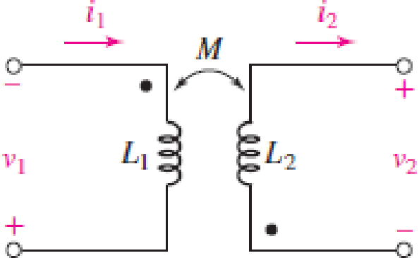
With respect to Fig. 13.36, assume L1 = 500 mH, L2 = 250 mH, and M = 20 mH. Determine the steady-state expression for (a) v1 if i1 = 0 and i2 = 3 cos 80t A; (b) v2 if i1 = 4 cos (30t − 15°) A and i2 = 0. (c) Repeat parts (a) and (b) if M is increased to 200 mH.
FIGURE 13.36
Expert Solution & Answer
Want to see the full answer?
Check out a sample textbook solution
Students have asked these similar questions
1. A series circuit contains a resistance of 55.1 ohms and the voltage across through it has equation
of e = 230 cos(314t – 50°) V. Determine the current equation and the power equation and the
instantaneous current and power at t = 2.2ms. Determine also the average power in the circuit.
2. A series circuit contains an inductor of 36.3mH inductance and the current flowing through it is
defined by i =
15.2 sin(360t + 52.2°) A. Determine the voltage applied across the circuit and its
value at t= 5.5ms. Determine also the power equation, instantaneous power att=5.5ms and average
power.
Fundamentals of Electrical Engineering 2020/2021
Dr. Yaseen H. Tahir
xample: (example 15-3, page 388, David) (H. W.)
A 1 MF capacitance is to be constructed from rolled-up sheets of
aluminum foil separated by a layer of paper 0.1 mm thick. Calculate the
required area for each sheet of foil if the relative permittivity of the
paper is 6.
Jution:
Time left 0
A resistor of 42 ohm is connected in series with a capacitor of 50 micro farad. if a supply of 240 V, 60 Hz is
connected across the arrangement then the current flowing in the capacitor is.
O a. 3.14 A
O b. 35.4 A
O c. 31.4 A
O d. 3.54 A
Chapter 13 Solutions
Loose Leaf for Engineering Circuit Analysis Format: Loose-leaf
Ch. 13.1 - Assuming M = 10 H, coil L2 is open-circuited, and...Ch. 13.1 - For the circuit of Fig. 13.9, write appropriate...Ch. 13.1 - For the circuit of Fig. 13.11, write an...Ch. 13.2 - Let is = 2 cos 10t A in the circuit of Fig. 13.14,...Ch. 13.3 - Element values for a certain linear transformer...Ch. 13.3 - (a) If the two networks shown in Fig. 13.20 are...Ch. 13.3 - If the networks in Fig. 13.23 are equivalent,...Ch. 13.4 - Prob. 8PCh. 13.4 - Let N1 = 1000 turns and N2 = 5000 turns in the...Ch. 13 - Prob. 1E
Ch. 13 - With respect to Fig. 13.36, assume L1 = 500 mH, L2...Ch. 13 - The circuit in Fig. 13.36 has a sinusoidal input...Ch. 13 - Prob. 4ECh. 13 - Prob. 5ECh. 13 - The circuit in Fig. 13.38 has a sinusoidal input...Ch. 13 - The physical construction of three pairs of...Ch. 13 - Prob. 8ECh. 13 - Prob. 9ECh. 13 - Calculate v1 and v2 if i1 = 5 sin 40t mA and i2 =...Ch. 13 - Prob. 11ECh. 13 - For the circuit of Fig. 13.41, calculate I1, I2,...Ch. 13 - Prob. 13ECh. 13 - Prob. 14ECh. 13 - In the circuit of Fig. 13.43, M is reduced by an...Ch. 13 - Prob. 16ECh. 13 - Prob. 17ECh. 13 - Prob. 18ECh. 13 - Prob. 19ECh. 13 - Note that there is no mutual coupling between the...Ch. 13 - Prob. 21ECh. 13 - (a) Find Zin(j) for the network of Fig 13.50. (b)...Ch. 13 - For the coupled coils of Fig. 13.51, L1 = L2 = 10...Ch. 13 - Prob. 24ECh. 13 - Prob. 25ECh. 13 - Prob. 26ECh. 13 - Consider the circuit represented in Fig. 13.53....Ch. 13 - Compute v1, v2, and the average power delivered to...Ch. 13 - Assume the following values for the circuit...Ch. 13 - Prob. 30ECh. 13 - Prob. 31ECh. 13 - Prob. 32ECh. 13 - Prob. 33ECh. 13 - Prob. 34ECh. 13 - Prob. 35ECh. 13 - Prob. 36ECh. 13 - Prob. 37ECh. 13 - FIGURE 13.60 For the circuit of Fig. 13.60, redraw...Ch. 13 - Prob. 39ECh. 13 - Prob. 40ECh. 13 - Calculate the average power delivered to the 400 m...Ch. 13 - Prob. 42ECh. 13 - Calculate the average power delivered to each...Ch. 13 - Prob. 44ECh. 13 - Prob. 45ECh. 13 - Prob. 46ECh. 13 - Prob. 47ECh. 13 - Prob. 48ECh. 13 - A transformer whose nameplate reads 2300/230 V, 25...Ch. 13 - Prob. 52ECh. 13 - As the lead singer in the local rock band, you...Ch. 13 - Obtain an expression for V2/Vs in the circuit of...Ch. 13 - Prob. 55E
Knowledge Booster


Learn more about
Need a deep-dive on the concept behind this application? Look no further. Learn more about this topic, electrical-engineering and related others by exploring similar questions and additional content below.Similar questions
- Find a) capacitance b) Vdc filtered c) Vmax d) Vminarrow_forwardA 0.7-F capacitor is connected in series with a 9-ohm resistor. If the connection is energized from an 11-V DC source, determine which among the following is a differential equation describing the circuit? Let q be the amount of the charge in the circuit at any time t. O A. dq dt O B. dq dt O C. dq dt O D. dq dt + - 9 + 11 + 63 10 9 11 10 63 = = || 10 63 9 11 63 10 11 9arrow_forwardFundamentals of Electrical Engineering 2020/2021 Dr. Yaseen H. Tahir xample: (example 15-3, page 388, David) (H. W.) A1 MF capacitance is to be constructed from rolled-up sheets of aluminum foil separated by a layer of paper 0.1l mm thick. Calculate the required area for each sheet of foil if the relative permittivity of the paper is 6.arrow_forward
- Given a parallel RLC circuit comprised of the following element: 72.06-ohm resistor, ideal inductor with reactance of 69.81 ohms; and a capacitor with reactance of 10.98 ohms. Compute for reactive power in VArs given an ac voltage source of 100 cis 0 volts. Give only the absolute value. PLEASE ANSWER WITHIN 30 MINUTES. Round off to the nearest 4 decimal places. No Scientific notation. Do not round off in the middle of calculation. Use stored values. Write the numerical values only. No units in your final answer. Spaces are not allowed.arrow_forwardThe network Nc shown below in Figure 1.99(a) contains a combination of scaled capaci- tors in series and parallel connections. Using the vahues as shown, you are asked to do the following. (a) Calculate the value of the terminal capacitance Cab at terminals a-b. (b) To obtain an equivalent capacitance Ceq of 1.5F, Nc is to be placed either in series with a capacitance Cz as shown in Figure 1.99(b) or in parallel with Cx as shown in Figure 1.99(c). Determine which connection is correct and calculate the value of C; that will produce the value of 1.5F for Ceg- 4F 2F 3F 1F C OF (a) N. N. 2. (b) (c) Figure 1.99 (a) Capacitor combo Nc (b) Nc in series with C, (c) Ne in parallel with C,arrow_forwardSaved Messages Shared media A premaccs = Pinned message fr12345@notavaag.g O un SOLD 77 videos An uncharge capacitor in series with a 120-volt voltmeter os 10,000 ohms resistance is suddenly connected to a 100V battery. one second later, the voltmeter reads 60 volt. Determine the capacitance of the capacitor A 187.54 uF B 190.62 uF 197.76 uF D 192.23 uF * UNIQUE MARKET kay @premsbyjisoo mag dm: AVAIL 271 & TG SCAMMERS GC Photo 313 of 317 Upload Docu. 0 Spotify ava today at 11:56 AM WebAdvisorarrow_forward
- For the circuit below assuming an ideal switch, preform transient analysis to predict the voltage across resistor, R2 and plot the results. The inductor will have zero current as initial condition. L1 0.005 2 U1 100mH R1 1k V1 20Vdc R2 100arrow_forwardR1 1000 V1 C1 =1pF 12Vpk ~1kHz 0° Find the capacitor's reactance Xc, impedance Z, the circuit's current, and peak voltage across the resistor. Xc: ohms, Round to the nearest whole number. Do not include units. Z: ohms: Round to the nearest whole number. Do not include units. Current: mA : round to the nearest milliamp. Do not include units. Vr: Vpk round to the nearest TENTH. (1 decimal place) Do not include units. Hiarrow_forwardIf the input voltage for the given circuit below is 220 V at 50 Hz, the load resistance (RL) is 3300 and the average output voltage is 20 V. Assume the diodes to be germanium diodes. Determine the turns ratio of the transformer used. If a capacitor of 100 µF is connected parallel to the load resistor (RL), Determine the ripple factor. D1 D2 V D3 .... D4 RL a. The turns ratio of transformer (Npri/Nsec) is b. The Ripple factor is cell rellarrow_forward
- 1. What impedance vector 0 – j22 represents:A. A pure resistance.B. A pure inductance.C. A pure capacitance.D. An inductance combined with a resistance.arrow_forwardAns.a) 79580/Hb)1mH/m Problem: 2.6.12. A galvanometer has a coil resistance of 50 ohms and a current sensitivity of 0.001 micro-ampere per mm. How much is the voltage across its terminals when the deflection is 15 cm at full scale? Ans. 7.5µ V Problem: 2.6.13. A 40-F capacitor is charged to store 0.2 J of energy. An uncharged 60-µF capacitor is then connected in parallel with the first one through perfectly conducting leads. What is the final energy of the system? Ans. 0.12J Problem: 2.6.14. A 40-uF capacitor is connected in parallel with a 60-µF capacitor and across a time-varying voltage source. At a certain instant, the total current supplied by the source is 10 A. Determine the instantaneous currents through the individual capacitors. Ans. 4A and 6Aarrow_forwardShort Problem: Given a parallel RLC circuit comprised of the following element: 55.27-ohm resistor, ideal inductor with reactance of 33.87 ohms; and a capacitor with reactance of 14.68 ohms. Compute for reactive power in VArs given an ac voltage source of 100 cis 0 volts. Give only the absolute value. Note: Follow this reminder carefully. Compute to the nearest 4 decimal places. No Scientific notation. Do not round off in the middle of calculation. Use stored values. Write the numerical values only. No units in your final answer. Spaces are not allowed. Excessive number of decimals as compared to the required number of decimals may result to an incorrect answer.arrow_forward
arrow_back_ios
SEE MORE QUESTIONS
arrow_forward_ios
Recommended textbooks for you
 Introductory Circuit Analysis (13th Edition)Electrical EngineeringISBN:9780133923605Author:Robert L. BoylestadPublisher:PEARSON
 Delmar's Standard Textbook Of ElectricityElectrical EngineeringISBN:9781337900348Author:Stephen L. HermanPublisher:Cengage Learning
 Programmable Logic ControllersElectrical EngineeringISBN:9780073373843Author:Frank D. PetruzellaPublisher:McGraw-Hill Education
 Fundamentals of Electric CircuitsElectrical EngineeringISBN:9780078028229Author:Charles K Alexander, Matthew SadikuPublisher:McGraw-Hill Education
 Electric Circuits. (11th Edition)Electrical EngineeringISBN:9780134746968Author:James W. Nilsson, Susan RiedelPublisher:PEARSON
 Engineering ElectromagneticsElectrical EngineeringISBN:9780078028151Author:Hayt, William H. (william Hart), Jr, BUCK, John A.Publisher:Mcgraw-hill Education,
Introductory Circuit Analysis (13th Edition)
Electrical Engineering
ISBN:9780133923605
Author:Robert L. Boylestad
Publisher:PEARSON
Delmar's Standard Textbook Of Electricity
Electrical Engineering
ISBN:9781337900348
Author:Stephen L. Herman
Publisher:Cengage Learning
Programmable Logic Controllers
Electrical Engineering
ISBN:9780073373843
Author:Frank D. Petruzella
Publisher:McGraw-Hill Education
Fundamentals of Electric Circuits
Electrical Engineering
ISBN:9780078028229
Author:Charles K Alexander, Matthew Sadiku
Publisher:McGraw-Hill Education
Electric Circuits. (11th Edition)
Electrical Engineering
ISBN:9780134746968
Author:James W. Nilsson, Susan Riedel
Publisher:PEARSON
Engineering Electromagnetics
Electrical Engineering
ISBN:9780078028151
Author:Hayt, William H. (william Hart), Jr, BUCK, John A.
Publisher:Mcgraw-hill Education,
Inductors Explained - The basics how inductors work working principle; Author: The Engineering Mindset;https://www.youtube.com/watch?v=KSylo01n5FY;License: Standard Youtube License