
Loose Leaf for Engineering Circuit Analysis Format: Loose-leaf
9th Edition
ISBN: 9781259989452
Author: Hayt
Publisher: Mcgraw Hill Publishers
expand_more
expand_more
format_list_bulleted
Concept explainers
Videos
Textbook Question
Chapter 13, Problem 29E
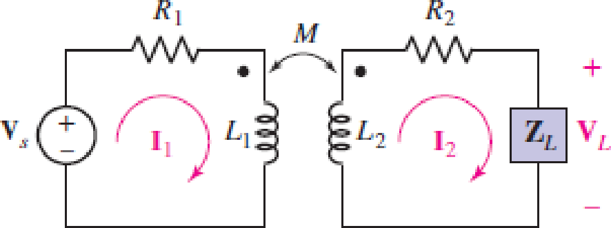
Assume the following values for the circuit depicted schematically in Fig. 13.16: R1 = R2 = 5 Ω, L1 = 2 μH, L2 = 1 μH, and M = 800 nH. Calculate the input impedance for ω = 107 rad/s if ZL is equal to (a) 1 Ω; (b) j Ω; (c) −j Ω; (d)  .
.
FIGURE 13.16 A linear transformer containing a source in the primary circuit and a load in the secondary circuit. Resistance is also included in both the primary and the secondary.
Expert Solution & Answer
Want to see the full answer?
Check out a sample textbook solution
Students have asked these similar questions
Problem 13.3- Enhanced with Hints and Feedback
Figure
+
1/sC2 V
b
CVo
1 of 1
Correct
Here we learn how to find the equivalent voltage VTL in a given circuit with components in the s domain.
Part B
Calculate the equivalent impedance.
Express your answer in terms of some or all of the variables Vo, s, I, C.
► View Available Hint(s)
ZTh=
Submit
15. ΑΣΦΑ
x² Xb
j+ CV
SC
vec
√x √x
Previous Answers
IXI T20 (X)* x.10n
X Incorrect; Try Again; 9 attempts remaining
The correct answer does not depend on: CVo. j.
?
For the circuit shown in Fig. 13.7a, find the ratio of the output
voltage across the 400
using phasor notation. With using S-domain
resistor to the source voltage, expressed
wwwm
www mer
j90 2
M = 9 H
i)1H EI00 H
V = 10/0° V
v = 10 cos 10t V
400 2
v2
jkN
400 N
W = 10 rad/s
j10n
(a)
(b)
I FIGURE 13.7 (a) A circuit containing mutual inductance in which the voltage ratio V2/V, is
desired. (b) Self- and mutual inductances are replaced by the corresponding impedances.
rell
Problem 13.2-19
The input to the circuit shown in the Figure is the voltage of the voltage source, vs. The output of the circuit is the capacitor voltage, vo. Determine
the values of the resistances R3 and R4, provided that R, = 10 kN and R, = 15 k2, required to cause the network function of the circuit to be
Vo(w)
Vs(w)
11
H(w)
(1+ j음)(1+ J100
10
R2
R3
R4
R1
Us
1 μΕ
Va
Up
1 μF
R3 =
k2, R4 =
Chapter 13 Solutions
Loose Leaf for Engineering Circuit Analysis Format: Loose-leaf
Ch. 13.1 - Assuming M = 10 H, coil L2 is open-circuited, and...Ch. 13.1 - For the circuit of Fig. 13.9, write appropriate...Ch. 13.1 - For the circuit of Fig. 13.11, write an...Ch. 13.2 - Let is = 2 cos 10t A in the circuit of Fig. 13.14,...Ch. 13.3 - Element values for a certain linear transformer...Ch. 13.3 - (a) If the two networks shown in Fig. 13.20 are...Ch. 13.3 - If the networks in Fig. 13.23 are equivalent,...Ch. 13.4 - Prob. 8PCh. 13.4 - Let N1 = 1000 turns and N2 = 5000 turns in the...Ch. 13 - Prob. 1E
Ch. 13 - With respect to Fig. 13.36, assume L1 = 500 mH, L2...Ch. 13 - The circuit in Fig. 13.36 has a sinusoidal input...Ch. 13 - Prob. 4ECh. 13 - Prob. 5ECh. 13 - The circuit in Fig. 13.38 has a sinusoidal input...Ch. 13 - The physical construction of three pairs of...Ch. 13 - Prob. 8ECh. 13 - Prob. 9ECh. 13 - Calculate v1 and v2 if i1 = 5 sin 40t mA and i2 =...Ch. 13 - Prob. 11ECh. 13 - For the circuit of Fig. 13.41, calculate I1, I2,...Ch. 13 - Prob. 13ECh. 13 - Prob. 14ECh. 13 - In the circuit of Fig. 13.43, M is reduced by an...Ch. 13 - Prob. 16ECh. 13 - Prob. 17ECh. 13 - Prob. 18ECh. 13 - Prob. 19ECh. 13 - Note that there is no mutual coupling between the...Ch. 13 - Prob. 21ECh. 13 - (a) Find Zin(j) for the network of Fig 13.50. (b)...Ch. 13 - For the coupled coils of Fig. 13.51, L1 = L2 = 10...Ch. 13 - Prob. 24ECh. 13 - Prob. 25ECh. 13 - Prob. 26ECh. 13 - Consider the circuit represented in Fig. 13.53....Ch. 13 - Compute v1, v2, and the average power delivered to...Ch. 13 - Assume the following values for the circuit...Ch. 13 - Prob. 30ECh. 13 - Prob. 31ECh. 13 - Prob. 32ECh. 13 - Prob. 33ECh. 13 - Prob. 34ECh. 13 - Prob. 35ECh. 13 - Prob. 36ECh. 13 - Prob. 37ECh. 13 - FIGURE 13.60 For the circuit of Fig. 13.60, redraw...Ch. 13 - Prob. 39ECh. 13 - Prob. 40ECh. 13 - Calculate the average power delivered to the 400 m...Ch. 13 - Prob. 42ECh. 13 - Calculate the average power delivered to each...Ch. 13 - Prob. 44ECh. 13 - Prob. 45ECh. 13 - Prob. 46ECh. 13 - Prob. 47ECh. 13 - Prob. 48ECh. 13 - A transformer whose nameplate reads 2300/230 V, 25...Ch. 13 - Prob. 52ECh. 13 - As the lead singer in the local rock band, you...Ch. 13 - Obtain an expression for V2/Vs in the circuit of...Ch. 13 - Prob. 55E
Knowledge Booster


Learn more about
Need a deep-dive on the concept behind this application? Look no further. Learn more about this topic, electrical-engineering and related others by exploring similar questions and additional content below.Similar questions
- Problem 13.2-22 The input to this circuit is the voltage of the voltage source, vs(t). The output is the voltage, vo(t), across the capacitor. 34 2 500 2 Vs (: 95 ia 3.5 mF Vo ia The network function of this circuit is Vo(w) Vs(w) a 1+ jbw H(w) = where a and b are real constants. Determine the values of a and b. a = and barrow_forwardThe diagram shown below is a typical tuning circuit. Considering this circuit comprises a transformer (with a coil ratio of 20:1 and an HV side voltage of 240V ), a capacitor of impedance -j20Ω, an inductor of impedance j40Ω, and a 50Ω resistor, determine: the current supplied by the source (0.2228) the impedance seen at the supply (HV side)(21540.55) the power dissipated by the resistor(2.482 watts) the operating power factor of the fitting(0.928 lagging) If the capacitor is now removed from the above circuit and is placed in parallel with the secondary of the transformer, redraw the circuit diagram and recalculate parts a. to d. in question (i). Draw the phasor diagram for both series and parallel RLC circuits in parts (i) and (ii). Discuss the effects of changing the capacitor connection in parallel on the power factor of the circuit. State the benefits of using the transformer in the above circuit. Explain the operating principle of the transformer with particular reference to…arrow_forwardHW18 13.16 Obtain the Norton equivalent at teminals a-b of the H circuit in Fig. 13.85. ps ML 8Ω 2Ω a 120/0° v (E j403 Ej60 { 22 j6 Ωarrow_forward
- 16. Consider the circuit of Fig. 13.46. The two sources are is1 = 2 cos t mA and is2 = 1.5 sin t mA. If M1 = 2 H, M2 = 0 H, and M3 = 10 H, calculate vAG(t). OA B M2 3 H C iş (1 20 H M1 M3 G I FIGURE 13.46 elll elll ellarrow_forwardThe parameters of a certain linear transformer are R, 100 Q. L =9H, L=4H andk=0,5. The transformer 200 2, R. couples an impedance consisting of an 800 Q resistor in series with a 1 uF capacitor to a sinusoidal voltage source. The 300 V (rms) source has an internal impedance of 500 +j100 Q and a frequency of 400 rad s. a) Construct a frequency-domain equivalent circuit of the system. b) Calculate the self-impedance of the primary circuit. c) Calculate the self-impedance of the secondary circuit. d) Calculate the impedance reflected into the primary winding. e) Calculate the scaling factor for the reflected impedance. f) Calculate the impedance seen looking into the primary terminals of the transformer. g) Calculate the Thevenin equivalent with respect to the terminals cd er Ed ucation. RE A RSCNarrow_forwardRepresent the II network of Fig. 13.60 as an equivalent linear transformer with zero initial currents if (a) La = 1 H, LB = 2 H, and Lc = 4 H; (b) LẠ = 10 mH, LB = 50 mH, and Lc= 22 mH. OC ll LB Lc LA OD BO rellarrow_forward
- 40. For the circuit shown in Fig. 13.66, find (a) I,: (h) I2; (c) I3: (d) P252; (e) P22: (S) P32. Figure 13.66 3 25 N 3:1 4:3 100/0° V rms ell ll elle elllarrow_forwardQuestion 4: Obtain the Thevenin equivalent circuit for the circuit in Fig. 13.83 at terminals a-b. 50/90° V (+ 5Ω Figure 13.83 m j6Ω j2 Ω α b m j8 Ω -j3 Ω 2 Ω Μ 20/0° Aarrow_forwardA transformer may be used to provide maximum power transfer between two AC circuits that have different impedances Z1 and Z2. This process is called impedance matching. (a) Show that the ratio of turns N1/N2 for thistransformer is N1/N2 =√Z1/Z2(b) Suppose you want to use a transformer as an impedance- matching device between an audio amplifier that has an output impedance of 8.00 kΩ and a speaker that has an input impedance of 8.00 Ω. What should your N1/N2 ratio be?arrow_forward
- FOR THE CIRCUIT SHOWN, WITH R1=10 Ω, R2=25 Ω, L1=90 mH, DETERMINE:A) THE VALUE INDICATED BY THE XMM1 INSTRUMENT.B) THE MINIMUM CAPACITY OF THE TRANSFORMER.C) THE REAL POWER SUPPLIED BY THE TRANSFORMER.D) THE VALUE OF THE CAPACITOR TO CORRECT THE POWER FACTOR TO 0.98 IN DELAY. EXPRESS THE VALUE IN uF.E) THE VALUE INDICATED BY THE XMM2 INSTRUMENT.arrow_forward21) 21. Find V₁ (jo) and V₂(jo) in terms of I, (jo) and 1₂(jw) for each circuit of Fig. 13.49. + V₁ www R₁ L₁ M FIGURE 13.49 (a) mm 1/3 R₂ + V₂ O + V₁ R₁ мет M (b) www R₂ L2 V₂ +arrow_forward18. For the circuit of Fig. 13.47, find the currents i(t), i2(1), and i3(t) if f = 60 Hz. %3D 50 4 H ell 3 H 2 sin 31 V ( 10 H 12 0 I3 elearrow_forward
arrow_back_ios
SEE MORE QUESTIONS
arrow_forward_ios
Recommended textbooks for you
 Introductory Circuit Analysis (13th Edition)Electrical EngineeringISBN:9780133923605Author:Robert L. BoylestadPublisher:PEARSON
 Delmar's Standard Textbook Of ElectricityElectrical EngineeringISBN:9781337900348Author:Stephen L. HermanPublisher:Cengage Learning
 Programmable Logic ControllersElectrical EngineeringISBN:9780073373843Author:Frank D. PetruzellaPublisher:McGraw-Hill Education
 Fundamentals of Electric CircuitsElectrical EngineeringISBN:9780078028229Author:Charles K Alexander, Matthew SadikuPublisher:McGraw-Hill Education
 Electric Circuits. (11th Edition)Electrical EngineeringISBN:9780134746968Author:James W. Nilsson, Susan RiedelPublisher:PEARSON
 Engineering ElectromagneticsElectrical EngineeringISBN:9780078028151Author:Hayt, William H. (william Hart), Jr, BUCK, John A.Publisher:Mcgraw-hill Education,
Introductory Circuit Analysis (13th Edition)
Electrical Engineering
ISBN:9780133923605
Author:Robert L. Boylestad
Publisher:PEARSON
Delmar's Standard Textbook Of Electricity
Electrical Engineering
ISBN:9781337900348
Author:Stephen L. Herman
Publisher:Cengage Learning
Programmable Logic Controllers
Electrical Engineering
ISBN:9780073373843
Author:Frank D. Petruzella
Publisher:McGraw-Hill Education
Fundamentals of Electric Circuits
Electrical Engineering
ISBN:9780078028229
Author:Charles K Alexander, Matthew Sadiku
Publisher:McGraw-Hill Education
Electric Circuits. (11th Edition)
Electrical Engineering
ISBN:9780134746968
Author:James W. Nilsson, Susan Riedel
Publisher:PEARSON
Engineering Electromagnetics
Electrical Engineering
ISBN:9780078028151
Author:Hayt, William H. (william Hart), Jr, BUCK, John A.
Publisher:Mcgraw-hill Education,
Current Divider Rule; Author: Neso Academy;https://www.youtube.com/watch?v=hRU1mKWUehY;License: Standard YouTube License, CC-BY