
Loose Leaf for Engineering Circuit Analysis Format: Loose-leaf
9th Edition
ISBN: 9781259989452
Author: Hayt
Publisher: Mcgraw Hill Publishers
expand_more
expand_more
format_list_bulleted
Concept explainers
Videos
Textbook Question
Chapter 13, Problem 7E
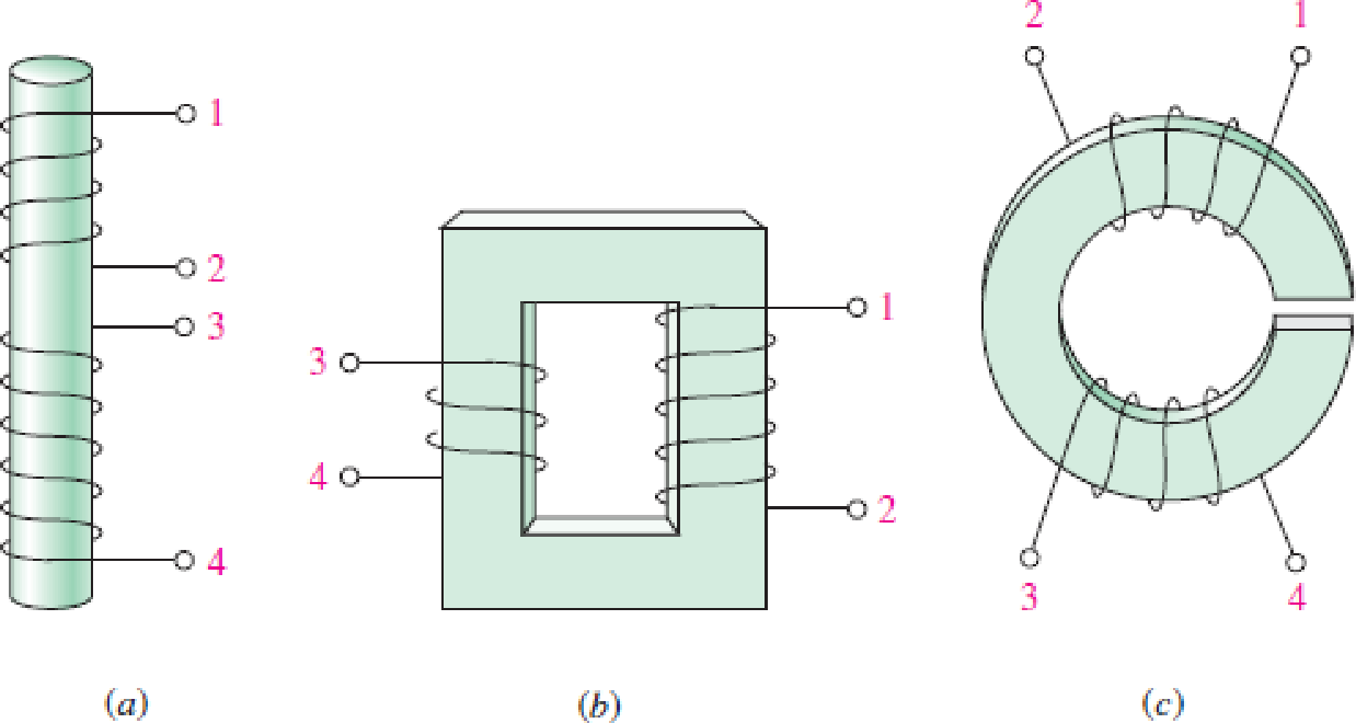
The physical construction of three pairs of coupled coils is shown in Fig. 13.39. Show the two different possible locations for the two dots on each pair of coils.
FIGURE 13.39
Expert Solution & Answer
Want to see the full answer?
Check out a sample textbook solution
Students have asked these similar questions
A coil has resistance of 5 ohm and inductive reactance of 4 ohm.
a) what is the impedance of the coil?
b) what is the admittance of the coil?
An ideal transformer has two secondary coils with number of turns 100 and 150respectively. Theprimary coil has 125 turns and supplied from 400 V, 50 Hz,single phase source. If the two secondarycoils are connected in series, the possible voltages across the series combination will be:(A) 833.5 V or 166.5 V (B) 833.5 V or 320 V (C) 320 V or 800 V (D) 800 V or 166.5 V
3- The self-inductance of an iron-cored coil is a function of:
a) The geometry of the coil only.
b) The current passing through it only.
c) The frequency of the applied voltage only.
d) All of the above factors.
4- The most effootiua
Chapter 13 Solutions
Loose Leaf for Engineering Circuit Analysis Format: Loose-leaf
Ch. 13.1 - Assuming M = 10 H, coil L2 is open-circuited, and...Ch. 13.1 - For the circuit of Fig. 13.9, write appropriate...Ch. 13.1 - For the circuit of Fig. 13.11, write an...Ch. 13.2 - Let is = 2 cos 10t A in the circuit of Fig. 13.14,...Ch. 13.3 - Element values for a certain linear transformer...Ch. 13.3 - (a) If the two networks shown in Fig. 13.20 are...Ch. 13.3 - If the networks in Fig. 13.23 are equivalent,...Ch. 13.4 - Prob. 8PCh. 13.4 - Let N1 = 1000 turns and N2 = 5000 turns in the...Ch. 13 - Prob. 1E
Ch. 13 - With respect to Fig. 13.36, assume L1 = 500 mH, L2...Ch. 13 - The circuit in Fig. 13.36 has a sinusoidal input...Ch. 13 - Prob. 4ECh. 13 - Prob. 5ECh. 13 - The circuit in Fig. 13.38 has a sinusoidal input...Ch. 13 - The physical construction of three pairs of...Ch. 13 - Prob. 8ECh. 13 - Prob. 9ECh. 13 - Calculate v1 and v2 if i1 = 5 sin 40t mA and i2 =...Ch. 13 - Prob. 11ECh. 13 - For the circuit of Fig. 13.41, calculate I1, I2,...Ch. 13 - Prob. 13ECh. 13 - Prob. 14ECh. 13 - In the circuit of Fig. 13.43, M is reduced by an...Ch. 13 - Prob. 16ECh. 13 - Prob. 17ECh. 13 - Prob. 18ECh. 13 - Prob. 19ECh. 13 - Note that there is no mutual coupling between the...Ch. 13 - Prob. 21ECh. 13 - (a) Find Zin(j) for the network of Fig 13.50. (b)...Ch. 13 - For the coupled coils of Fig. 13.51, L1 = L2 = 10...Ch. 13 - Prob. 24ECh. 13 - Prob. 25ECh. 13 - Prob. 26ECh. 13 - Consider the circuit represented in Fig. 13.53....Ch. 13 - Compute v1, v2, and the average power delivered to...Ch. 13 - Assume the following values for the circuit...Ch. 13 - Prob. 30ECh. 13 - Prob. 31ECh. 13 - Prob. 32ECh. 13 - Prob. 33ECh. 13 - Prob. 34ECh. 13 - Prob. 35ECh. 13 - Prob. 36ECh. 13 - Prob. 37ECh. 13 - FIGURE 13.60 For the circuit of Fig. 13.60, redraw...Ch. 13 - Prob. 39ECh. 13 - Prob. 40ECh. 13 - Calculate the average power delivered to the 400 m...Ch. 13 - Prob. 42ECh. 13 - Calculate the average power delivered to each...Ch. 13 - Prob. 44ECh. 13 - Prob. 45ECh. 13 - Prob. 46ECh. 13 - Prob. 47ECh. 13 - Prob. 48ECh. 13 - A transformer whose nameplate reads 2300/230 V, 25...Ch. 13 - Prob. 52ECh. 13 - As the lead singer in the local rock band, you...Ch. 13 - Obtain an expression for V2/Vs in the circuit of...Ch. 13 - Prob. 55E
Knowledge Booster


Learn more about
Need a deep-dive on the concept behind this application? Look no further. Learn more about this topic, electrical-engineering and related others by exploring similar questions and additional content below.Similar questions
- 13. A coil has a resistance of 6 ohms and an inductance of 0.02 H. When a non-inductive resistor is connected in series with the coil, the current drawn when connected to a 220 V DC source is equal to the current drawn by the coil alone across a 220 V, 60 Hz source. Determine the resistance of the non- inductive resistor. A) 3.63 0 B. 6.39 N C. 3.69 N D. 3.96 Narrow_forward2- When the frequency of the voltage across of a (50HZ) power transformer increased by 10% of the rated value, the no-load current: a) Increased. b) Decreased. c) Remains the same. 3- The self-inductance of an iron-cored coil is a function of: a) The geometry of the coil only. b) The current passing through it only. c) The frequency of the applied voltage only. d) All of the above factors. 4- The most effective factor on the value of the percentage impedance drop of a transformer is: a) The geometry of the coilarrow_forward2- When the frequency of the voltage across of a (50HZ) power transformer increased by 10% of the rated value, the no-load current: a) Increased. b) Decreased. c) Remains the same. 3- The self-inductance of an iron-cored coil is a function of: a) The geometry of the coil only. b) The current passing through it only. c) The frequency of the applied voltage only. d) All of the above factors.arrow_forward
- The open-circuit voltage of 246 V and the full load secondary voltage of 222 V, then the % regulation of a transformer is The temperature measurement capability of thermistors is from 200°C to over 2000°C. Select one: True Falsearrow_forward-0.1 Hint: The solid green dots indicate polarity. 10 Questio -10 The ideal transformer shown in figure below has N₂/N₁=10. The ratio V₂/V₁ is: 1:n Aurima @WPA MacBook Proarrow_forwardAn ideal transformer is rated 12 kVA, 3600/120V, 60 Hz. Find the transformation ratio if the 120V is the secondary voltage. a = Find the current rating of the secondary if the 120V is the secondary voltage. units Is rating Find the current rating of the primary if the 120V is the secondary voltage. Ip rating unitsarrow_forward
- An ideal auto-transformer has its secondary winding labelled as a, b and c. The primary winding has 100 turns. The number of turns on the secondary side are 400 turns between a and b and 200 turns between b and c. The total number of turns between a and c is 600 turns. The transformer supplies a resistive load of 6 kW between a and c. In addition, a load of impedance 1,000 cis (45°) ohms is connected between a and b. For a primary voltage of 1,000 V, find the primary current and primary input power.arrow_forwardkindly help me with this problem thank you so much! Instructions: Evaluate and Show neat, logical, and complete solution.show final answers in four decimal places. 1. The primary coil of a power transformer has an inductance of 30 mH with negligible resistance. Find its inductive reactance at a frequency of 60 Hz and current it will draw a 120 V line.arrow_forwardWhat is the impedance of a transformer coil that has 340' of #18 copper wire and an inductance of 70mH at 60Hz? 1000’ of #18 copper wire is 16 ohms.arrow_forward
- A transformer with a primary of 1500 turns is used to generate 10V ac from A supply voltage of 120 V. How many turns are there on the secondary? If the secondary is loaded with 22 ohms resistor, What is the primary current? Please solve the problem, in the subject Industrial electronics. Thank youarrow_forward10- The type of insulation is an important choice in transformer design because: a) It determines the winding cross-sectional area. b) It reduces the iron losses. c) It reduces the inrush current. Q.5. Assign the following statements hy "1 It jg Iarrow_forwardIV- Transformer Design You are requested to design a transformer which will have the following characteristics: Two windings, one primary and one secondary with an E-shape core. Vin = 220 V RMS 16 s Vout < 20 v RMS open circuits 14.5 V < Vout s 16 V on a 100 N resistor. 2 VA < S 35 VA apparent power. Show all steps of your design with calculation. - Indicate current in primary and secondary in both open circuit and with 100 n resistor. Simulate your transformer and show both input and output voltage with the 100 Ω load. Talk about your transformer and wire sizes.arrow_forward
arrow_back_ios
SEE MORE QUESTIONS
arrow_forward_ios
Recommended textbooks for you
 Introductory Circuit Analysis (13th Edition)Electrical EngineeringISBN:9780133923605Author:Robert L. BoylestadPublisher:PEARSON
 Delmar's Standard Textbook Of ElectricityElectrical EngineeringISBN:9781337900348Author:Stephen L. HermanPublisher:Cengage Learning
 Programmable Logic ControllersElectrical EngineeringISBN:9780073373843Author:Frank D. PetruzellaPublisher:McGraw-Hill Education
 Fundamentals of Electric CircuitsElectrical EngineeringISBN:9780078028229Author:Charles K Alexander, Matthew SadikuPublisher:McGraw-Hill Education
 Electric Circuits. (11th Edition)Electrical EngineeringISBN:9780134746968Author:James W. Nilsson, Susan RiedelPublisher:PEARSON
 Engineering ElectromagneticsElectrical EngineeringISBN:9780078028151Author:Hayt, William H. (william Hart), Jr, BUCK, John A.Publisher:Mcgraw-hill Education,
Introductory Circuit Analysis (13th Edition)
Electrical Engineering
ISBN:9780133923605
Author:Robert L. Boylestad
Publisher:PEARSON
Delmar's Standard Textbook Of Electricity
Electrical Engineering
ISBN:9781337900348
Author:Stephen L. Herman
Publisher:Cengage Learning
Programmable Logic Controllers
Electrical Engineering
ISBN:9780073373843
Author:Frank D. Petruzella
Publisher:McGraw-Hill Education
Fundamentals of Electric Circuits
Electrical Engineering
ISBN:9780078028229
Author:Charles K Alexander, Matthew Sadiku
Publisher:McGraw-Hill Education
Electric Circuits. (11th Edition)
Electrical Engineering
ISBN:9780134746968
Author:James W. Nilsson, Susan Riedel
Publisher:PEARSON
Engineering Electromagnetics
Electrical Engineering
ISBN:9780078028151
Author:Hayt, William H. (william Hart), Jr, BUCK, John A.
Publisher:Mcgraw-hill Education,
TRANSFORMERS - What They Are, How They Work, How Electricians Size Them; Author: Electrician U;https://www.youtube.com/watch?v=tXPy4OE7ApE;License: Standard Youtube License