
Loose Leaf for Engineering Circuit Analysis Format: Loose-leaf
9th Edition
ISBN: 9781259989452
Author: Hayt
Publisher: Mcgraw Hill Publishers
expand_more
expand_more
format_list_bulleted
Concept explainers
Videos
Textbook Question
Chapter 13, Problem 20E
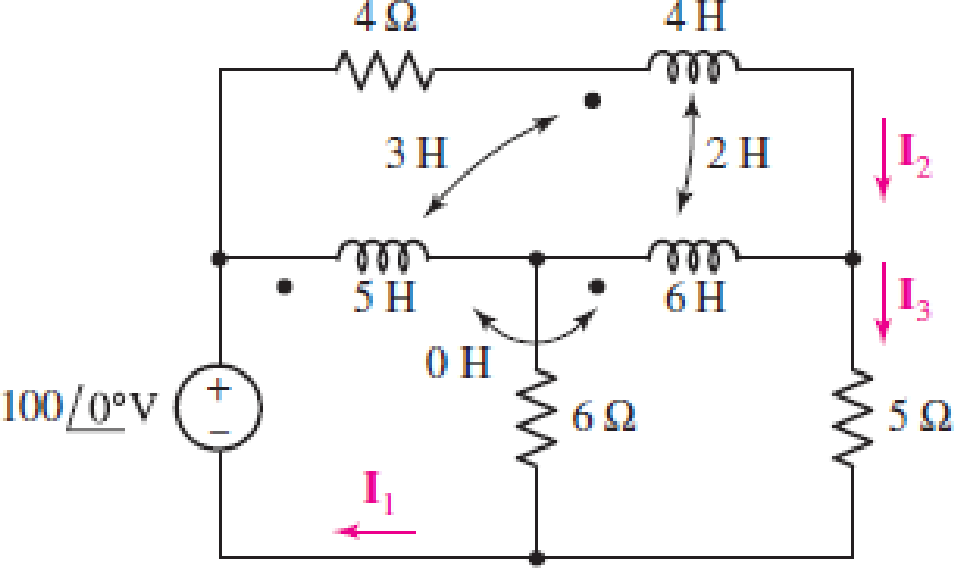
Note that there is no mutual coupling between the 5 H and 6 H inductors in the circuit of Fig. 13.48. (a) Write a set of equations in terms of I1(jω), I2(jω), and I3(jω). (b) Find I3(jω), if (b) ω = 2 rad/s.
FIGURE 13.48
Expert Solution & Answer
Want to see the full answer?
Check out a sample textbook solution
Students have asked these similar questions
What is the impedance of a transformer coil that has 340' of #18 copper wire and an inductance of 70mH at 60Hz?
1000’ of #18 copper wire is 16 ohms.
Fundamentals of Electrical Engineering 2020/2021
Dr. Yaseen H. Tahir
xample: (example 15-3, page 388, David) (H. W.)
A 1 MF capacitance is to be constructed from rolled-up sheets of
aluminum foil separated by a layer of paper 0.1 mm thick. Calculate the
required area for each sheet of foil if the relative permittivity of the
paper is 6.
Jution:
If a Marx generator is required to perform a 170 kV lightning impulse
test, and you have capacitors rated at 60 kVdc available:
(a)
If the voltage efficiency is 90%, how many stages, n, should the
Marx generator have, and what should the dc charging voltage,
Vo, be?
Using the output parameters to calculate the erected
capacitance first, what should be the capacitance per stage if
the minimum required stored energy for the test is 900 J?
(b)
Chapter 13 Solutions
Loose Leaf for Engineering Circuit Analysis Format: Loose-leaf
Ch. 13.1 - Assuming M = 10 H, coil L2 is open-circuited, and...Ch. 13.1 - For the circuit of Fig. 13.9, write appropriate...Ch. 13.1 - For the circuit of Fig. 13.11, write an...Ch. 13.2 - Let is = 2 cos 10t A in the circuit of Fig. 13.14,...Ch. 13.3 - Element values for a certain linear transformer...Ch. 13.3 - (a) If the two networks shown in Fig. 13.20 are...Ch. 13.3 - If the networks in Fig. 13.23 are equivalent,...Ch. 13.4 - Prob. 8PCh. 13.4 - Let N1 = 1000 turns and N2 = 5000 turns in the...Ch. 13 - Prob. 1E
Ch. 13 - With respect to Fig. 13.36, assume L1 = 500 mH, L2...Ch. 13 - The circuit in Fig. 13.36 has a sinusoidal input...Ch. 13 - Prob. 4ECh. 13 - Prob. 5ECh. 13 - The circuit in Fig. 13.38 has a sinusoidal input...Ch. 13 - The physical construction of three pairs of...Ch. 13 - Prob. 8ECh. 13 - Prob. 9ECh. 13 - Calculate v1 and v2 if i1 = 5 sin 40t mA and i2 =...Ch. 13 - Prob. 11ECh. 13 - For the circuit of Fig. 13.41, calculate I1, I2,...Ch. 13 - Prob. 13ECh. 13 - Prob. 14ECh. 13 - In the circuit of Fig. 13.43, M is reduced by an...Ch. 13 - Prob. 16ECh. 13 - Prob. 17ECh. 13 - Prob. 18ECh. 13 - Prob. 19ECh. 13 - Note that there is no mutual coupling between the...Ch. 13 - Prob. 21ECh. 13 - (a) Find Zin(j) for the network of Fig 13.50. (b)...Ch. 13 - For the coupled coils of Fig. 13.51, L1 = L2 = 10...Ch. 13 - Prob. 24ECh. 13 - Prob. 25ECh. 13 - Prob. 26ECh. 13 - Consider the circuit represented in Fig. 13.53....Ch. 13 - Compute v1, v2, and the average power delivered to...Ch. 13 - Assume the following values for the circuit...Ch. 13 - Prob. 30ECh. 13 - Prob. 31ECh. 13 - Prob. 32ECh. 13 - Prob. 33ECh. 13 - Prob. 34ECh. 13 - Prob. 35ECh. 13 - Prob. 36ECh. 13 - Prob. 37ECh. 13 - FIGURE 13.60 For the circuit of Fig. 13.60, redraw...Ch. 13 - Prob. 39ECh. 13 - Prob. 40ECh. 13 - Calculate the average power delivered to the 400 m...Ch. 13 - Prob. 42ECh. 13 - Calculate the average power delivered to each...Ch. 13 - Prob. 44ECh. 13 - Prob. 45ECh. 13 - Prob. 46ECh. 13 - Prob. 47ECh. 13 - Prob. 48ECh. 13 - A transformer whose nameplate reads 2300/230 V, 25...Ch. 13 - Prob. 52ECh. 13 - As the lead singer in the local rock band, you...Ch. 13 - Obtain an expression for V2/Vs in the circuit of...Ch. 13 - Prob. 55E
Knowledge Booster


Learn more about
Need a deep-dive on the concept behind this application? Look no further. Learn more about this topic, electrical-engineering and related others by exploring similar questions and additional content below.Similar questions
- 13. Given Ll 32s sin t;L (163 +1) a) d) tsint sint b) sin c) tsin 4arrow_forwardQ1) a). A 1.5 H coil has R of 70 2. The coil is energised by e = 149 sin 314 t. obtain the expression for the transient component of the current flowing through the coil after the voltage is suddenly switched on. b). Based on Figures la,lb and le and RLC elements, write a discussion on voltage-current relations and power factor. Im Im 4 Im 4 0. Re Re Re Figure la. Figure Ib. Figure le.arrow_forwardA coil having an inductance of 200 mH is magnetically coupled to another coil having an inductance of 500 mH. The coefficient of coupling between the coils is 0.65. Calculate the equivalent inductance if the coils are connected in parallel aiding HTML Editorarrow_forward
- Two identical coils with self-inductance of 250 µH each are connected in series. When connected series aiding, the equivalent inductance is 550 µH and 450 µH when connected in series opposing. How much is the coupling coefficient of two coils? a. 0.2 b. 0.3 c. 0.1 d. 0.4arrow_forwardA coil in a 60-Hz circuit has a resistance of 100 N and an inductance of 0.45 H. Calculate (a) the coil's reactance and (b) the circuit's impedance. *Please make sure the full solution is viewable and does not cut off.arrow_forwardQUESTION 58 Short Problem: Given a parallel RLC circuit comprised of the following element: 94.42-ohm resistor, ideal inductor with reactance of 60.84 ohms; and a capacitor with reactance of 15.03 ohms. Compute for reactive power in VArs given an ac voltage source of 100 cis 0 volts. Give only the absolute value. Note: Follow this reminder carefully. Compute to the nearest 4 decimal places. No Scientific notation. Do not round off in the middle of calculation. Use stored values. Write the numerical values only. No units in your final answer. Spaces are not allowed. Excessive number of decimals as compared to the required number of decimals may result to an incorrect answer.arrow_forward
- Fundamentals of Electrical Engineering 2020/2021 Dr. Yaseen H. Tahir xample: (example 15-3, page 388, David) (H. W.) A1 MF capacitance is to be constructed from rolled-up sheets of aluminum foil separated by a layer of paper 0.1l mm thick. Calculate the required area for each sheet of foil if the relative permittivity of the paper is 6.arrow_forwardSaved Messages Shared media A premaccs = Pinned message fr12345@notavaag.g O un SOLD 77 videos An uncharge capacitor in series with a 120-volt voltmeter os 10,000 ohms resistance is suddenly connected to a 100V battery. one second later, the voltmeter reads 60 volt. Determine the capacitance of the capacitor A 187.54 uF B 190.62 uF 197.76 uF D 192.23 uF * UNIQUE MARKET kay @premsbyjisoo mag dm: AVAIL 271 & TG SCAMMERS GC Photo 313 of 317 Upload Docu. 0 Spotify ava today at 11:56 AM WebAdvisorarrow_forwardR1 1000 V1 C1 =1pF 12Vpk ~1kHz 0° Find the capacitor's reactance Xc, impedance Z, the circuit's current, and peak voltage across the resistor. Xc: ohms, Round to the nearest whole number. Do not include units. Z: ohms: Round to the nearest whole number. Do not include units. Current: mA : round to the nearest milliamp. Do not include units. Vr: Vpk round to the nearest TENTH. (1 decimal place) Do not include units. Hiarrow_forward
- A coil has resistance of 5 ohm and capacitive reactance of 6 ohm . a) what is the impedance of the coil? b) what is the admittance of the coil?arrow_forwardHW17 13.14 Obtain the Thevenin equivalent circuit for the circuit in Fig. 13.83 at terminals a-b. j22 -j32 H j8 N 50 ll ll j6Q a 10/90° V 4/0° Aarrow_forwardThe total inductance of two coils, 1 and 2, when connected in series is 0.8 H or 0.5 H respectively on the relative directions of the current in the coils. Coil 1, when isolated from coil 2, has a self-inductance of 0.5 H. Calculate the coupling factor or coefficient between the coils. Answer is 43.3%. Show solution.arrow_forward
arrow_back_ios
SEE MORE QUESTIONS
arrow_forward_ios
Recommended textbooks for you
 Introductory Circuit Analysis (13th Edition)Electrical EngineeringISBN:9780133923605Author:Robert L. BoylestadPublisher:PEARSON
 Delmar's Standard Textbook Of ElectricityElectrical EngineeringISBN:9781337900348Author:Stephen L. HermanPublisher:Cengage Learning
 Programmable Logic ControllersElectrical EngineeringISBN:9780073373843Author:Frank D. PetruzellaPublisher:McGraw-Hill Education
 Fundamentals of Electric CircuitsElectrical EngineeringISBN:9780078028229Author:Charles K Alexander, Matthew SadikuPublisher:McGraw-Hill Education
 Electric Circuits. (11th Edition)Electrical EngineeringISBN:9780134746968Author:James W. Nilsson, Susan RiedelPublisher:PEARSON
 Engineering ElectromagneticsElectrical EngineeringISBN:9780078028151Author:Hayt, William H. (william Hart), Jr, BUCK, John A.Publisher:Mcgraw-hill Education,
Introductory Circuit Analysis (13th Edition)
Electrical Engineering
ISBN:9780133923605
Author:Robert L. Boylestad
Publisher:PEARSON
Delmar's Standard Textbook Of Electricity
Electrical Engineering
ISBN:9781337900348
Author:Stephen L. Herman
Publisher:Cengage Learning
Programmable Logic Controllers
Electrical Engineering
ISBN:9780073373843
Author:Frank D. Petruzella
Publisher:McGraw-Hill Education
Fundamentals of Electric Circuits
Electrical Engineering
ISBN:9780078028229
Author:Charles K Alexander, Matthew Sadiku
Publisher:McGraw-Hill Education
Electric Circuits. (11th Edition)
Electrical Engineering
ISBN:9780134746968
Author:James W. Nilsson, Susan Riedel
Publisher:PEARSON
Engineering Electromagnetics
Electrical Engineering
ISBN:9780078028151
Author:Hayt, William H. (william Hart), Jr, BUCK, John A.
Publisher:Mcgraw-hill Education,
TRANSFORMERS - What They Are, How They Work, How Electricians Size Them; Author: Electrician U;https://www.youtube.com/watch?v=tXPy4OE7ApE;License: Standard Youtube License