
Loose Leaf for Engineering Circuit Analysis Format: Loose-leaf
9th Edition
ISBN: 9781259989452
Author: Hayt
Publisher: Mcgraw Hill Publishers
expand_more
expand_more
format_list_bulleted
Concept explainers
Videos
Textbook Question
Chapter 5, Problem 17E
- (a) Determine the current labeled i in the circuit of Fig. 5.61 after first transforming the circuit such that it contains only resistors and voltage sources.
- (b) Simulate each circuit to verify the same current flows in both cases.
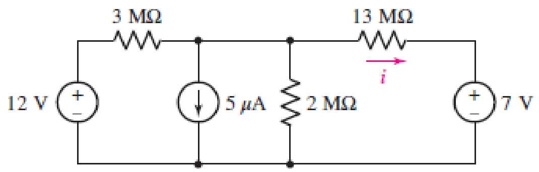
■ FIGURE 5.61
Expert Solution & Answer
Want to see the full answer?
Check out a sample textbook solution
Students have asked these similar questions
Digital lab & design
The circuits don’t have to be created in proteus project just a normal drawing on paper will do, thanks.
3)
Q17. For the circuit shown in Figure 5.23
calculate (a) the value of resistor Rx such
that the total power dissipated in the circuit
is 2.5kW, and (b) the current flowing in
each of the four resistors.
4 Rq=15 2
a A3=38 2
R2=10 2
Rx
12
14
V2²
250 V
If no node was encountered more than once, then the set of nodes and elements that we have
passed through is defined as a closed path.
Select one:
O True
False
Chapter 5 Solutions
Loose Leaf for Engineering Circuit Analysis Format: Loose-leaf
Ch. 5.1 - For the circuit of Fig. 5.4, use superposition to...Ch. 5.2 - For the circuit of Fig. 5.7, use superposition to...Ch. 5.2 - For the circuit of Fig. 5.18, compute the current...Ch. 5.2 - For the circuit of Fig. 5.20, compute the voltage...Ch. 5.3 - Using repeated source transformations, determine...Ch. 5.3 - Use Thvenins theorem to find the current through...Ch. 5.3 - Determine the Thvenin and Norton equivalents of...Ch. 5.3 - Find the Thvenin equivalent for the network of...Ch. 5.3 - Find the Thvenin equivalent for the network of...Ch. 5.4 - Consider the circuit of Fig. 5.43. FIGURE 5.43...
Ch. 5.5 - Prob. 11PCh. 5 - Linear systems are so easy to work with that...Ch. 5 - Prob. 2ECh. 5 - Prob. 3ECh. 5 - (a) Employ superposition to determine the current...Ch. 5 - (a) Using superposition to consider each source...Ch. 5 - (a) Determine the individual contributions of each...Ch. 5 - (a) Determine the individual contributions of each...Ch. 5 - After studying the circuit of Fig. 5.53, change...Ch. 5 - Consider the three circuits shown in Fig. 5.54....Ch. 5 - (a) Using superposition, determine the voltage...Ch. 5 - Employ superposition principles to obtain a value...Ch. 5 - (a) Employ superposition to determine the...Ch. 5 - Perform an appropriate source transformation on...Ch. 5 - (a) For the circuit of Fig. 5.59, plot iL versus...Ch. 5 - Determine the current labeled I in the circuit of...Ch. 5 - Verify that the power absorbed by the 7 resistor...Ch. 5 - (a) Determine the current labeled i in the circuit...Ch. 5 - (a) Using repeated source transformations, reduce...Ch. 5 - Prob. 19ECh. 5 - (a) Making use of repeated source transformations,...Ch. 5 - Prob. 21ECh. 5 - (a) With the assistance of source transformations,...Ch. 5 - For the circuit in Fig. 5.67 transform all...Ch. 5 - Prob. 24ECh. 5 - (a) Referring to Fig. 5.69, determine the Thevenin...Ch. 5 - (a) With respect to the circuit depicted in Fig....Ch. 5 - (a) Obtain the Norton equivalent of the network...Ch. 5 - (a) Determine the Thevenin equivalent of the...Ch. 5 - Referring to the circuit of Fig. 5.71: (a)...Ch. 5 - Prob. 30ECh. 5 - (a) Employ Thvenins theorem to obtain a...Ch. 5 - Prob. 32ECh. 5 - Determine the Norton equivalent of the circuit...Ch. 5 - For the circuit of Fig. 5.75: (a) Employ Nortons...Ch. 5 - (a) Obtain a value for the Thvenin equivalent...Ch. 5 - Prob. 36ECh. 5 - Obtain a value for the Thvenin equivalent...Ch. 5 - With regard to the network depicted in Fig. 5.79,...Ch. 5 - Determine the Thvenin and Norton equivalents of...Ch. 5 - Determine the Norton equivalent of the circuit...Ch. 5 - Prob. 41ECh. 5 - Determine the Thvenin and Norton equivalents of...Ch. 5 - Prob. 43ECh. 5 - Prob. 44ECh. 5 - Prob. 45ECh. 5 - (a) For the simple circuit of Fig. 5.87, find the...Ch. 5 - For the circuit drawn in Fig. 5.88, (a) determine...Ch. 5 - Study the circuit of Fig. 5.89. (a) Determine the...Ch. 5 - Prob. 49ECh. 5 - Prob. 50ECh. 5 - With reference to the circuit of Fig. 5.91, (a)...Ch. 5 - Prob. 52ECh. 5 - Select a value for RL in Fig. 5.93 such that it...Ch. 5 - Determine what value of resistance would absorb...Ch. 5 - Derive the equations required to convert from a...Ch. 5 - Convert the - (or "-") connected networks in Fig....Ch. 5 - Convert the Y-(or T-) connected networks in Fig....Ch. 5 - For the network of Fig. 5.97, select a value of R...Ch. 5 - For the network of Fig. 5.98, select a value of R...Ch. 5 - Prob. 60ECh. 5 - Calculate Rin as indicated in Fig.5.100. FIGURE...Ch. 5 - Employ Y conversion techniques as appropriate to...Ch. 5 - Prob. 63ECh. 5 - (a) Use appropriate techniques to obtain both the...Ch. 5 - (a) For the network in Fig. 5.104, replace the...Ch. 5 - Prob. 66ECh. 5 - Prob. 67ECh. 5 - A 2.57 load is connected between terminals a and...Ch. 5 - A load resistor is connected across the open...Ch. 5 - A backup is required for the circuit depicted in...Ch. 5 - (a) Explain in general terms how source...Ch. 5 - The load resistor in Fig. 5.108 can safely...Ch. 5 - Prob. 74ECh. 5 - As part of a security system, a very thin 100 ...Ch. 5 - With respect to the circuit in Fig. 5.90, (a)...
Knowledge Booster


Learn more about
Need a deep-dive on the concept behind this application? Look no further. Learn more about this topic, electrical-engineering and related others by exploring similar questions and additional content below.Similar questions
- LMH_chapter3-part 1-homework [Protected View] PowerPoint ĐĂNG PHẠM HỒNG File Home Insert Design Transitions Animations Slide Show Review View Help Tell me what you want to do & Share 4 HW16 5.13 Find u, and i, in the circuit of Fig. 5.52. HW18 10 ka 1vO 100 ka 90 ka 10 ka 5.20 In the circuit of Fig. 5.59, calculate v, of v; = 0. 50 k2 8 kQ HW17 ww 5.14 Determine the output voltage v, in the circuit of 5.53. 10 ka 2 k2 10 ka 20 ka 4 k2 4 k2 Sma O 5 kQ www ww 6. 9 V HW18 5.20 In the circuit of Fig. 5.59, calculate v, of v; = 0. 8 ka 4 ka 4 ka ww 7 HW19 3.24 In the circuit shown in Fig. 5.62, find k in the voltage tYansfer flunction ,- b, R. 6. ww-arrow_forward6. a) Use the mesh-current method to write a complete set of equations that could be used to solve this circuit. Do not simplify the circuit. Do not attempt to solve or simplify your equations. Define all variables. b) Compare the number of equations required using the node-voltage method and the mesh current method, for this circuit. Which method requires fewer equations? 32[0] 24[Q] 28[Q] 11[O]ix 31[Q) 30[0] | 2[V] 33[Q] i 34[Q] 35[0] 3[A] 38[0] 29[0] 10[O]i 4[V] Vr 36[2] 37[0] 6[A] 5[V] 25[0]arrow_forwardKindly solve what is ask and provide complete solution so that I can understand. Also, I want a handwritten solution. Thank you so much.:arrow_forward
- Find the current across the resistor 5 52 while the switch S is open for a long time. A) (A) B)(A) C) (A) 3 V 192 ΖΩΣ D) (A) 26 3ΩΣ 5 V E) (A) 4 V www :552arrow_forwardDetermine the Equivalent Resistance (Rab) of the circuit. ( please provide illustrations/drawings it is needed for our solutions)arrow_forwardCan someone please help me out and provide the full solution and answer for this example, I need it as my reviewer. Thank you so much!arrow_forward
- 6:06 A e-learning.hct.edu.om Question: A group of Students from UTAS (Physics Unit) visit Al Hassan Electrical laboratory. Their supervisor gives them instruction about use of Resistors in different electrical appliances. Students are provided with four resistors R,=50 ohm, R2=70 ohm, R3=380 ohm, R4=70 ohm and a battery of 40 v. i) If students connect these four resistances in series, what is the effective resistance? ii) If students connect these four resistances in parallel, what is the effective resistance? iii) If students connect 40 V battery across series combination, what is the current flowing in the circuit? iv) If students connect 40 V battery across parallel combination, what is the current flowing in the circuit? v) If students connect these four resistances shown below, what is the voltage across points a and d? R2 R1 R4 b. R3 V Finish attempt...arrow_forwardSoru 5. (2 puan) Which circuit is the logical equivalent of the Reference Circuit? A A B Reference Circuit (A) A A A B В X D (B) (C) (D) A Figure (B) В Figure (C) Figure (A) D NONE OF THEM E Figure (D)arrow_forwardConsider an approximate model of the epitaxial resistivity in a silicon power transistor:A pyramid structure with a square base has a resistor in every edge of the structure.The structure of the model is shown below. (a) Based on the description above, draw the relevant structure and include relevant resistors in your diagram. (b) Suppose the value of all resistors is R Ω, calculate the total resistance viewing from any of the a-x pairs. (c) Is the total resistance similar for all possible vertex pairs? Verify your statement above by including relevant calculation proof.arrow_forward
- Consider a 2.5kW PV system exposed to sun for 6 hours with the solar intensity of 1 sun. Calculate the total PV power generation for 3 years. Also, calculate the loss in PV power generation if the solar intensity is reduced to 0.8 sun and 0.5 sun. [Estimated time to solve: 8 min]arrow_forwardQuestion 18 a) Using repeated source transformations, reduce the circuit of Fig. 5.62 to a voltage source in series with a resistor, both of which are in series with the 6 MS2 resistor. b) Calculate the power dissipated by the 6 MS2 resistor using your simplified circuit. 27 ΜΑ (1) FIGURE 5.62 3.5 ΜΩ www 750 ΚΩ 1.2 ΜΩ 15 V 7 ΜΩ 6 ΜΩarrow_forwardUsing ∆-Y / Y-∆ transformation, calcuate total resistance.As you solve the circuit, present the new configurations and the full answer. To four decimal places, round your answers.arrow_forward
arrow_back_ios
SEE MORE QUESTIONS
arrow_forward_ios
Recommended textbooks for you
 Introductory Circuit Analysis (13th Edition)Electrical EngineeringISBN:9780133923605Author:Robert L. BoylestadPublisher:PEARSON
 Delmar's Standard Textbook Of ElectricityElectrical EngineeringISBN:9781337900348Author:Stephen L. HermanPublisher:Cengage Learning
 Programmable Logic ControllersElectrical EngineeringISBN:9780073373843Author:Frank D. PetruzellaPublisher:McGraw-Hill Education
 Fundamentals of Electric CircuitsElectrical EngineeringISBN:9780078028229Author:Charles K Alexander, Matthew SadikuPublisher:McGraw-Hill Education
 Electric Circuits. (11th Edition)Electrical EngineeringISBN:9780134746968Author:James W. Nilsson, Susan RiedelPublisher:PEARSON
 Engineering ElectromagneticsElectrical EngineeringISBN:9780078028151Author:Hayt, William H. (william Hart), Jr, BUCK, John A.Publisher:Mcgraw-hill Education,
Introductory Circuit Analysis (13th Edition)
Electrical Engineering
ISBN:9780133923605
Author:Robert L. Boylestad
Publisher:PEARSON
Delmar's Standard Textbook Of Electricity
Electrical Engineering
ISBN:9781337900348
Author:Stephen L. Herman
Publisher:Cengage Learning
Programmable Logic Controllers
Electrical Engineering
ISBN:9780073373843
Author:Frank D. Petruzella
Publisher:McGraw-Hill Education
Fundamentals of Electric Circuits
Electrical Engineering
ISBN:9780078028229
Author:Charles K Alexander, Matthew Sadiku
Publisher:McGraw-Hill Education
Electric Circuits. (11th Edition)
Electrical Engineering
ISBN:9780134746968
Author:James W. Nilsson, Susan Riedel
Publisher:PEARSON
Engineering Electromagnetics
Electrical Engineering
ISBN:9780078028151
Author:Hayt, William H. (william Hart), Jr, BUCK, John A.
Publisher:Mcgraw-hill Education,
Z Parameters - Impedance Parameters; Author: Electrical Engineering Authority;https://www.youtube.com/watch?v=qoD4AoNmySA;License: Standard Youtube License