
Loose Leaf for Engineering Circuit Analysis Format: Loose-leaf
9th Edition
ISBN: 9781259989452
Author: Hayt
Publisher: Mcgraw Hill Publishers
expand_more
expand_more
format_list_bulleted
Concept explainers
Videos
Textbook Question
Chapter 5, Problem 64E
(a) Use appropriate techniques to obtain both the Thévenin and Norton equivalents of the network drawn in Fig. 5.103. (b) Verify your answers by simulating each of the three circuits connected to a 1 Ω resistor.
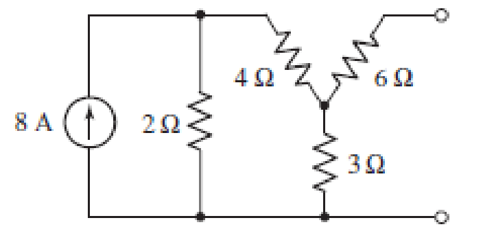
■ FIGURE 5.103
Expert Solution & Answer
Want to see the full answer?
Check out a sample textbook solution
Students have asked these similar questions
Question 48
Study the circuit of Fig. 5.89.
a) Determine the Norton equivalent connected to resistor Rout.
b) Select a value for Rout such that maximum power will be delivered to it.
4 A
FIGURE 5.89
ΚΩ
3 V
2 V
2 kΩ
Rout
Question 27
a) Obtain the Norton equivalent of the network connected to R₂ in Fig. 5.70.
Obtain the Thévenin equivalent of the same network.
b)
c) Use either to calculate i, for R₂ = 0 2,1 2, 4.923 , and 8.107 2.
1 A
FIGURE 5.70
5Ω
5Ω
0.8 Ω
202
RL
19. (a) Using as many source transformations and element combination techniques
as required, simplify the circuit of Fig. 5.63 so that it contains only the 7 V
source, a single resistor, and one other voltage source. (b) Verify that the 7 V
source delivers the same amount of power in both circuits.
3Ω
7V
2 A
3Ω
5 A
Chapter 5 Solutions
Loose Leaf for Engineering Circuit Analysis Format: Loose-leaf
Ch. 5.1 - For the circuit of Fig. 5.4, use superposition to...Ch. 5.2 - For the circuit of Fig. 5.7, use superposition to...Ch. 5.2 - For the circuit of Fig. 5.18, compute the current...Ch. 5.2 - For the circuit of Fig. 5.20, compute the voltage...Ch. 5.3 - Using repeated source transformations, determine...Ch. 5.3 - Use Thvenins theorem to find the current through...Ch. 5.3 - Determine the Thvenin and Norton equivalents of...Ch. 5.3 - Find the Thvenin equivalent for the network of...Ch. 5.3 - Find the Thvenin equivalent for the network of...Ch. 5.4 - Consider the circuit of Fig. 5.43. FIGURE 5.43...
Ch. 5.5 - Prob. 11PCh. 5 - Linear systems are so easy to work with that...Ch. 5 - Prob. 2ECh. 5 - Prob. 3ECh. 5 - (a) Employ superposition to determine the current...Ch. 5 - (a) Using superposition to consider each source...Ch. 5 - (a) Determine the individual contributions of each...Ch. 5 - (a) Determine the individual contributions of each...Ch. 5 - After studying the circuit of Fig. 5.53, change...Ch. 5 - Consider the three circuits shown in Fig. 5.54....Ch. 5 - (a) Using superposition, determine the voltage...Ch. 5 - Employ superposition principles to obtain a value...Ch. 5 - (a) Employ superposition to determine the...Ch. 5 - Perform an appropriate source transformation on...Ch. 5 - (a) For the circuit of Fig. 5.59, plot iL versus...Ch. 5 - Determine the current labeled I in the circuit of...Ch. 5 - Verify that the power absorbed by the 7 resistor...Ch. 5 - (a) Determine the current labeled i in the circuit...Ch. 5 - (a) Using repeated source transformations, reduce...Ch. 5 - Prob. 19ECh. 5 - (a) Making use of repeated source transformations,...Ch. 5 - Prob. 21ECh. 5 - (a) With the assistance of source transformations,...Ch. 5 - For the circuit in Fig. 5.67 transform all...Ch. 5 - Prob. 24ECh. 5 - (a) Referring to Fig. 5.69, determine the Thevenin...Ch. 5 - (a) With respect to the circuit depicted in Fig....Ch. 5 - (a) Obtain the Norton equivalent of the network...Ch. 5 - (a) Determine the Thevenin equivalent of the...Ch. 5 - Referring to the circuit of Fig. 5.71: (a)...Ch. 5 - Prob. 30ECh. 5 - (a) Employ Thvenins theorem to obtain a...Ch. 5 - Prob. 32ECh. 5 - Determine the Norton equivalent of the circuit...Ch. 5 - For the circuit of Fig. 5.75: (a) Employ Nortons...Ch. 5 - (a) Obtain a value for the Thvenin equivalent...Ch. 5 - Prob. 36ECh. 5 - Obtain a value for the Thvenin equivalent...Ch. 5 - With regard to the network depicted in Fig. 5.79,...Ch. 5 - Determine the Thvenin and Norton equivalents of...Ch. 5 - Determine the Norton equivalent of the circuit...Ch. 5 - Prob. 41ECh. 5 - Determine the Thvenin and Norton equivalents of...Ch. 5 - Prob. 43ECh. 5 - Prob. 44ECh. 5 - Prob. 45ECh. 5 - (a) For the simple circuit of Fig. 5.87, find the...Ch. 5 - For the circuit drawn in Fig. 5.88, (a) determine...Ch. 5 - Study the circuit of Fig. 5.89. (a) Determine the...Ch. 5 - Prob. 49ECh. 5 - Prob. 50ECh. 5 - With reference to the circuit of Fig. 5.91, (a)...Ch. 5 - Prob. 52ECh. 5 - Select a value for RL in Fig. 5.93 such that it...Ch. 5 - Determine what value of resistance would absorb...Ch. 5 - Derive the equations required to convert from a...Ch. 5 - Convert the - (or "-") connected networks in Fig....Ch. 5 - Convert the Y-(or T-) connected networks in Fig....Ch. 5 - For the network of Fig. 5.97, select a value of R...Ch. 5 - For the network of Fig. 5.98, select a value of R...Ch. 5 - Prob. 60ECh. 5 - Calculate Rin as indicated in Fig.5.100. FIGURE...Ch. 5 - Employ Y conversion techniques as appropriate to...Ch. 5 - Prob. 63ECh. 5 - (a) Use appropriate techniques to obtain both the...Ch. 5 - (a) For the network in Fig. 5.104, replace the...Ch. 5 - Prob. 66ECh. 5 - Prob. 67ECh. 5 - A 2.57 load is connected between terminals a and...Ch. 5 - A load resistor is connected across the open...Ch. 5 - A backup is required for the circuit depicted in...Ch. 5 - (a) Explain in general terms how source...Ch. 5 - The load resistor in Fig. 5.108 can safely...Ch. 5 - Prob. 74ECh. 5 - As part of a security system, a very thin 100 ...Ch. 5 - With respect to the circuit in Fig. 5.90, (a)...
Knowledge Booster


Learn more about
Need a deep-dive on the concept behind this application? Look no further. Learn more about this topic, electrical-engineering and related others by exploring similar questions and additional content below.Similar questions
- Find the current across the resistor 5 52 while the switch S is open for a long time. A) (A) B)(A) C) (A) 3 V 192 ΖΩΣ D) (A) 26 3ΩΣ 5 V E) (A) 4 V www :552arrow_forwardLMH_chapter3-part 1-homework [Protected View] PowerPoint ĐĂNG PHẠM HỒNG File Home Insert Design Transitions Animations Slide Show Review View Help Tell me what you want to do & Share 6. HW18 5.20 In the circuit of Fig. 5.59, calculate v, of v; = 0. HW20 8 ka 4 4 ka 5.32 Calculate iz and v, in the circuit of Fig. 5.70. Find the power dissipated by the 30-kN resistor. 7 HW19 3.24 In the circuit shown in Fig 5.62, find k in the voltage transfer flunction ,- , 48 k2 ww ww 8 4 mV 50 k2 HW20 60 k2 30 Ω 5.32 Calculate i, and e, in the circuit of Fig. 5.70. Find the power dissipated by the 30 kl resistor 10 kΩ 4 mv ( 50 ka 60 30 k2 10 k2 9. HW21 5.33 Re:kn lo the p m tineuit in Fip 571 Caknulale4 ud the pomer disupated by dhe kil resistor. 1 kI 8 3 ma O ww- wwarrow_forwardLMH_chapter3-part 1-homework [Protected View] PowerPoint ĐĂNG PHẠM HỒNG File Home Insert Design Transitions Animations Slide Show Review View Help Tell me what you want to do & Share 4 HW16 5.13 Find u, and i, in the circuit of Fig. 5.52. HW18 10 ka 1vO 100 ka 90 ka 10 ka 5.20 In the circuit of Fig. 5.59, calculate v, of v; = 0. 50 k2 8 kQ HW17 ww 5.14 Determine the output voltage v, in the circuit of 5.53. 10 ka 2 k2 10 ka 20 ka 4 k2 4 k2 Sma O 5 kQ www ww 6. 9 V HW18 5.20 In the circuit of Fig. 5.59, calculate v, of v; = 0. 8 ka 4 ka 4 ka ww 7 HW19 3.24 In the circuit shown in Fig. 5.62, find k in the voltage tYansfer flunction ,- b, R. 6. ww-arrow_forward
- Question 30 a) Employ Thévenin's theorem to obtain a simple two-component equivalent of the circuit shown in Fig. 5.72. b) Use your equivalent circuit to determine the power delivered to a 100 2 resistor connected to the open terminals. c) Verify your solution by analyzing the original circuit with the same 100 2 resistor connected across the open terminals. 45 Ω QTVⒸ 1 0.7 V FIGURE 5.72 75 Ω ww 122 02 220 Ω wwo 0.3 Aarrow_forwardQuestion 18 a) Using repeated source transformations, reduce the circuit of Fig. 5.62 to a voltage source in series with a resistor, both of which are in series with the 6 MS2 resistor. b) Calculate the power dissipated by the 6 MS2 resistor using your simplified circuit. 27 ΜΑ (1) FIGURE 5.62 3.5 ΜΩ www 750 ΚΩ 1.2 ΜΩ 15 V 7 ΜΩ 6 ΜΩarrow_forward1. For each configuration in Fig. 5.88, find the individaal (not combinations of) elements (voltage sources and/or resis- Lors) that are in serics. N R (a) (b) (e) (4) 一章arrow_forward
- 24. With regard to the circuit represented in Fig. 5.68, first transform both voltage sources to current sources, reduce the number of elements as much as possible, and determine the voltage v3. 6 0 + V3 203 2 Varrow_forwardHomework: Obtain vo in the circuit of the following figure. 5.3 30 V 20 V 4 kS2 2 k2 5 k2 Answer 20 Varrow_forwardConsider an approximate model of the epitaxial resistivity in a silicon power transistor:A pyramid structure with a square base has a resistor in every edge of the structure.The structure of the model is shown below. (a) Based on the description above, draw the relevant structure and include relevant resistors in your diagram. (b) Suppose the value of all resistors is R Ω, calculate the total resistance viewing from any of the a-x pairs. (c) Is the total resistance similar for all possible vertex pairs? Verify your statement above by including relevant calculation proof.arrow_forward
- A coil of 12 Ω resistance is in parallel with a coil of 20 Ω resistance. This combination is connected in series with a third coil of 8 Ω resistance. If the whole circuit is connected across a battery having an e.m.f. of 30 V and an internal resistance of 2 Ω, calculate (a) the terminal voltage of the battery and (b) the power in the 12 Ω coil.arrow_forwardQuestion 41 With regard to the circuit of Fig. 5.82, determine the power dissipated by a) a 1 k resistor connected between a and b; b) a 4.7 k2 resistor connected between a and b; c) a 10.54 k resistor connected between a and b. ao bo 10 ΚΩ V₁ FIGURE 5.82 IV +- 20 ΚΩ 0.02v1arrow_forwardKindly solve what is ask and provide complete solution so that I can understand. Also, I want a handwritten solution. Thank you so much.:arrow_forward
arrow_back_ios
SEE MORE QUESTIONS
arrow_forward_ios
Recommended textbooks for you
 Introductory Circuit Analysis (13th Edition)Electrical EngineeringISBN:9780133923605Author:Robert L. BoylestadPublisher:PEARSON
 Delmar's Standard Textbook Of ElectricityElectrical EngineeringISBN:9781337900348Author:Stephen L. HermanPublisher:Cengage Learning
 Programmable Logic ControllersElectrical EngineeringISBN:9780073373843Author:Frank D. PetruzellaPublisher:McGraw-Hill Education
 Fundamentals of Electric CircuitsElectrical EngineeringISBN:9780078028229Author:Charles K Alexander, Matthew SadikuPublisher:McGraw-Hill Education
 Electric Circuits. (11th Edition)Electrical EngineeringISBN:9780134746968Author:James W. Nilsson, Susan RiedelPublisher:PEARSON
 Engineering ElectromagneticsElectrical EngineeringISBN:9780078028151Author:Hayt, William H. (william Hart), Jr, BUCK, John A.Publisher:Mcgraw-hill Education,
Introductory Circuit Analysis (13th Edition)
Electrical Engineering
ISBN:9780133923605
Author:Robert L. Boylestad
Publisher:PEARSON
Delmar's Standard Textbook Of Electricity
Electrical Engineering
ISBN:9781337900348
Author:Stephen L. Herman
Publisher:Cengage Learning
Programmable Logic Controllers
Electrical Engineering
ISBN:9780073373843
Author:Frank D. Petruzella
Publisher:McGraw-Hill Education
Fundamentals of Electric Circuits
Electrical Engineering
ISBN:9780078028229
Author:Charles K Alexander, Matthew Sadiku
Publisher:McGraw-Hill Education
Electric Circuits. (11th Edition)
Electrical Engineering
ISBN:9780134746968
Author:James W. Nilsson, Susan Riedel
Publisher:PEARSON
Engineering Electromagnetics
Electrical Engineering
ISBN:9780078028151
Author:Hayt, William H. (william Hart), Jr, BUCK, John A.
Publisher:Mcgraw-hill Education,
Z Parameters - Impedance Parameters; Author: Electrical Engineering Authority;https://www.youtube.com/watch?v=qoD4AoNmySA;License: Standard Youtube License