
Loose Leaf for Engineering Circuit Analysis Format: Loose-leaf
9th Edition
ISBN: 9781259989452
Author: Hayt
Publisher: Mcgraw Hill Publishers
expand_more
expand_more
format_list_bulleted
Videos
Textbook Question
Chapter 5, Problem 8E
After studying the circuit of Fig. 5.53, change both voltage source values such that (a) i1 doubles; (b) the direction of i1 reverses, but its magnitude is unchanged.
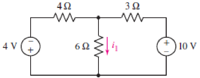
■ FIGURE 5.53
Expert Solution & Answer
Want to see the full answer?
Check out a sample textbook solution
Students have asked these similar questions
O
50
15. Why should design our circuits to operate below the SRF of electrical
elements?
to increase the gain
to make the circuit simple
None of them
to reduce the power used in the circuit.
to avoid the unexpected behavoir
Clear form
Page 1 of 1
Submit
Never submit passwords through Google Forms.
Solving #15, I do not understand how to calculate Vth
5.25 For the circuit involving an ideal voltage follower shown in the image below, if
R1 = 10 k2 and R2 = 16 k2, determine the output voltage vo Please pay
attention: the numbers may change since they are randomized. Your answer must
include 2 places after the decimal point, and the proper SI unit.
R,
15 V
Your Answer:
Answer
units
Chapter 5 Solutions
Loose Leaf for Engineering Circuit Analysis Format: Loose-leaf
Ch. 5.1 - For the circuit of Fig. 5.4, use superposition to...Ch. 5.2 - For the circuit of Fig. 5.7, use superposition to...Ch. 5.2 - For the circuit of Fig. 5.18, compute the current...Ch. 5.2 - For the circuit of Fig. 5.20, compute the voltage...Ch. 5.3 - Using repeated source transformations, determine...Ch. 5.3 - Use Thvenins theorem to find the current through...Ch. 5.3 - Determine the Thvenin and Norton equivalents of...Ch. 5.3 - Find the Thvenin equivalent for the network of...Ch. 5.3 - Find the Thvenin equivalent for the network of...Ch. 5.4 - Consider the circuit of Fig. 5.43. FIGURE 5.43...
Ch. 5.5 - Prob. 11PCh. 5 - Linear systems are so easy to work with that...Ch. 5 - Prob. 2ECh. 5 - Prob. 3ECh. 5 - (a) Employ superposition to determine the current...Ch. 5 - (a) Using superposition to consider each source...Ch. 5 - (a) Determine the individual contributions of each...Ch. 5 - (a) Determine the individual contributions of each...Ch. 5 - After studying the circuit of Fig. 5.53, change...Ch. 5 - Consider the three circuits shown in Fig. 5.54....Ch. 5 - (a) Using superposition, determine the voltage...Ch. 5 - Employ superposition principles to obtain a value...Ch. 5 - (a) Employ superposition to determine the...Ch. 5 - Perform an appropriate source transformation on...Ch. 5 - (a) For the circuit of Fig. 5.59, plot iL versus...Ch. 5 - Determine the current labeled I in the circuit of...Ch. 5 - Verify that the power absorbed by the 7 resistor...Ch. 5 - (a) Determine the current labeled i in the circuit...Ch. 5 - (a) Using repeated source transformations, reduce...Ch. 5 - Prob. 19ECh. 5 - (a) Making use of repeated source transformations,...Ch. 5 - Prob. 21ECh. 5 - (a) With the assistance of source transformations,...Ch. 5 - For the circuit in Fig. 5.67 transform all...Ch. 5 - Prob. 24ECh. 5 - (a) Referring to Fig. 5.69, determine the Thevenin...Ch. 5 - (a) With respect to the circuit depicted in Fig....Ch. 5 - (a) Obtain the Norton equivalent of the network...Ch. 5 - (a) Determine the Thevenin equivalent of the...Ch. 5 - Referring to the circuit of Fig. 5.71: (a)...Ch. 5 - Prob. 30ECh. 5 - (a) Employ Thvenins theorem to obtain a...Ch. 5 - Prob. 32ECh. 5 - Determine the Norton equivalent of the circuit...Ch. 5 - For the circuit of Fig. 5.75: (a) Employ Nortons...Ch. 5 - (a) Obtain a value for the Thvenin equivalent...Ch. 5 - Prob. 36ECh. 5 - Obtain a value for the Thvenin equivalent...Ch. 5 - With regard to the network depicted in Fig. 5.79,...Ch. 5 - Determine the Thvenin and Norton equivalents of...Ch. 5 - Determine the Norton equivalent of the circuit...Ch. 5 - Prob. 41ECh. 5 - Determine the Thvenin and Norton equivalents of...Ch. 5 - Prob. 43ECh. 5 - Prob. 44ECh. 5 - Prob. 45ECh. 5 - (a) For the simple circuit of Fig. 5.87, find the...Ch. 5 - For the circuit drawn in Fig. 5.88, (a) determine...Ch. 5 - Study the circuit of Fig. 5.89. (a) Determine the...Ch. 5 - Prob. 49ECh. 5 - Prob. 50ECh. 5 - With reference to the circuit of Fig. 5.91, (a)...Ch. 5 - Prob. 52ECh. 5 - Select a value for RL in Fig. 5.93 such that it...Ch. 5 - Determine what value of resistance would absorb...Ch. 5 - Derive the equations required to convert from a...Ch. 5 - Convert the - (or "-") connected networks in Fig....Ch. 5 - Convert the Y-(or T-) connected networks in Fig....Ch. 5 - For the network of Fig. 5.97, select a value of R...Ch. 5 - For the network of Fig. 5.98, select a value of R...Ch. 5 - Prob. 60ECh. 5 - Calculate Rin as indicated in Fig.5.100. FIGURE...Ch. 5 - Employ Y conversion techniques as appropriate to...Ch. 5 - Prob. 63ECh. 5 - (a) Use appropriate techniques to obtain both the...Ch. 5 - (a) For the network in Fig. 5.104, replace the...Ch. 5 - Prob. 66ECh. 5 - Prob. 67ECh. 5 - A 2.57 load is connected between terminals a and...Ch. 5 - A load resistor is connected across the open...Ch. 5 - A backup is required for the circuit depicted in...Ch. 5 - (a) Explain in general terms how source...Ch. 5 - The load resistor in Fig. 5.108 can safely...Ch. 5 - Prob. 74ECh. 5 - As part of a security system, a very thin 100 ...Ch. 5 - With respect to the circuit in Fig. 5.90, (a)...
Knowledge Booster


Learn more about
Need a deep-dive on the concept behind this application? Look no further. Learn more about this topic, electrical-engineering and related others by exploring similar questions and additional content below.Similar questions
- Given the circuit below, which of the below value(s) would change if the inductance value were doubled? Assume the circuit has been in this position for some time prior to the switching event happening. Multiple correct answers may exist. Select any/all that apply! t=0 30 12 V (+ 3H 202 40: energy stored prior to the switching event inductor current initial condition time constant energy stored when the system reaches steady-state inductor current final condition None of these answers are correct 402arrow_forwardQuestion 1 Multichannel reverberation can b (T_(m))/(T_(o))=1+(n)/(50) What value for n would produce 5=1+(n)/(50).arrow_forward31. For the circuit of Figure 5.71, determine the Thévenin equivalent that drives the 20 nF capacitor. 1 sin2pi100t a 91 20 nF 50 nF Figure 5.71arrow_forward
- Quèstion 1 In ac analysis of transistor biasing circuits, coupling capacitors should be open circuit. True False Moving to another question will save this response. hparrow_forwardThis solution states 10,000 / (220*√3) = 25. However, I cannot find a single calculator to reproduce this outcome, even if I suspend normal order of operations. Can you please revise? Without deducting from my question limit?arrow_forwardR1 For the above circuit, use the RTh short circuit method to determine the short circuit current, Isc, in Amps across the (a,b) terminals. Round your answer to the nearest single digit decimal place and do not enter units. Given that I = 11A R1 =72 R2 =52 R, =60 RL =52 Determine Isc in Ampsarrow_forward
- Procedure (A) Buck Converter (Duty Cycle) 1. Make connections of power supply, capacitor, inductor, MOSFET and load resistor to build the buck converter. Vs=100 V=18 r=0.5% R=10 ohm f=40 KH Calculate minimum inductance: Lmin=(1-D)( R)/2f Calculate minimum capacitance: Cmin=1-D/8L(AVo/No) f^2 Calculate duty ratio: D=Vo/Vinarrow_forwardExplain in detail the difference between a Micro-Electronics / Photonics Engineer and an Electronic Circuit Design Engineer. Be specific and provide details. Please cite all your sources. • Could these engineers have projects in common? Give examples answer all twoarrow_forwardA voltage of .... appears between the terminals of a combination of a 100 mF capacitor and a 12 oms resistor in parallel. Calculate the power absorbed by the parallel combination. Note: I leave the image of the exercises in Spanish, but it is easy to understand. Also in the other image is the correct final answer, for checking.arrow_forward
- Q17. For the circuit shown in Figure 5.23 calculate (a) the value of resistor Rx such that the total power dissipated in the circuit is 2.5kW, and (b) the current flowing in each of the four resistors. 4 Rq=15 2 a A3=38 2 R2=10 2 Rx 12 14 V2² 250 Varrow_forward5. 7.25 PSPICEMULTISIM The switch in the circuit isclosed at t=0 after being open for a long time. 1. a) Find i1(0−) and i2(0−)arrow_forwardWhere do we use Auxiliary Systems including SCADA in electrical engineering? Can you please explain the basic principle of those and cite some examples? the longer answer the better I'll definitely give a like :)arrow_forward
arrow_back_ios
SEE MORE QUESTIONS
arrow_forward_ios
Recommended textbooks for you
 Introductory Circuit Analysis (13th Edition)Electrical EngineeringISBN:9780133923605Author:Robert L. BoylestadPublisher:PEARSON
 Delmar's Standard Textbook Of ElectricityElectrical EngineeringISBN:9781337900348Author:Stephen L. HermanPublisher:Cengage Learning
 Programmable Logic ControllersElectrical EngineeringISBN:9780073373843Author:Frank D. PetruzellaPublisher:McGraw-Hill Education
 Fundamentals of Electric CircuitsElectrical EngineeringISBN:9780078028229Author:Charles K Alexander, Matthew SadikuPublisher:McGraw-Hill Education
 Electric Circuits. (11th Edition)Electrical EngineeringISBN:9780134746968Author:James W. Nilsson, Susan RiedelPublisher:PEARSON
 Engineering ElectromagneticsElectrical EngineeringISBN:9780078028151Author:Hayt, William H. (william Hart), Jr, BUCK, John A.Publisher:Mcgraw-hill Education,
Introductory Circuit Analysis (13th Edition)
Electrical Engineering
ISBN:9780133923605
Author:Robert L. Boylestad
Publisher:PEARSON
Delmar's Standard Textbook Of Electricity
Electrical Engineering
ISBN:9781337900348
Author:Stephen L. Herman
Publisher:Cengage Learning
Programmable Logic Controllers
Electrical Engineering
ISBN:9780073373843
Author:Frank D. Petruzella
Publisher:McGraw-Hill Education
Fundamentals of Electric Circuits
Electrical Engineering
ISBN:9780078028229
Author:Charles K Alexander, Matthew Sadiku
Publisher:McGraw-Hill Education
Electric Circuits. (11th Edition)
Electrical Engineering
ISBN:9780134746968
Author:James W. Nilsson, Susan Riedel
Publisher:PEARSON
Engineering Electromagnetics
Electrical Engineering
ISBN:9780078028151
Author:Hayt, William H. (william Hart), Jr, BUCK, John A.
Publisher:Mcgraw-hill Education,
Routh Hurwitz Stability Criterion Basic Worked Example; Author: The Complete Guide to Everything;https://www.youtube.com/watch?v=CzzsR5FT-8U;License: Standard Youtube License